

Pressure variable exhausting channel
An exhaust channel and variable pressure technology, which is applied to vertical pipes, building components, buildings, etc., can solve the problems of complex design and calculation of the position of the heavy hammer, smoke back into the room, and gas flow rate drop.
- Summary
- Abstract
- Description
- Claims
- Application Information
AI Technical Summary
Problems solved by technology
Method used
Image

Examples
Embodiment 1
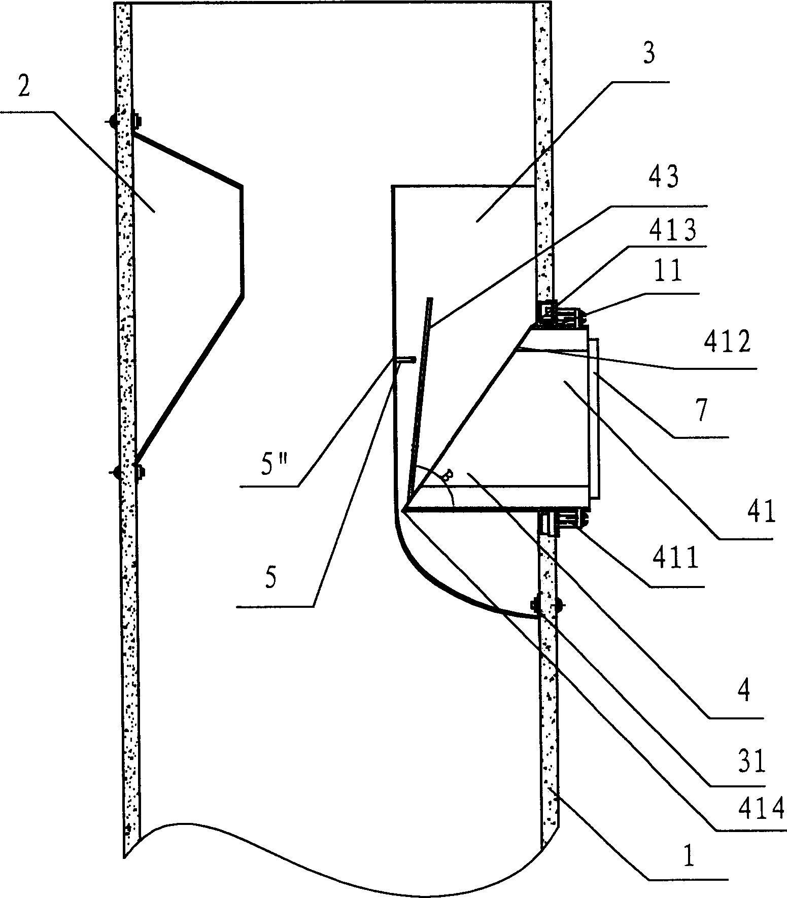
[0029] Embodiment one, see figure 1 , the figure shows a variable pressure exhaust channel, including a main pipe 1, a variable pressure plate 2, a guide pipe 3 and a diversion check exhaust valve 4; the guide pipe 3 is in the shape of a dustpan, and the opening is upward The flange 31 turned inward is fixed on the inner wall of the main pipe 1 and surrounds the air inlet 11 of the main pipe 1; Above; the diversion type check exhaust valve 4 is arranged at the air inlet 11 of the main pipeline 1; the diversion type check exhaust valve 4 includes a housing 41 and a valve plate 43, and the housing 41 is tubular and passes through the air inlet 11. The housing 41 is fixed on the wall outside the air inlet 11 of the main pipe 1 through a flange 411. The outlet end face 412 of the housing 41 is inclined, and the outlet end face 412 The apex 413 is roughly flush with the inner wall of the main pipe 1, and the lowest point 414 is located in the main pipe 1, close to the inner wall o...
Embodiment 2
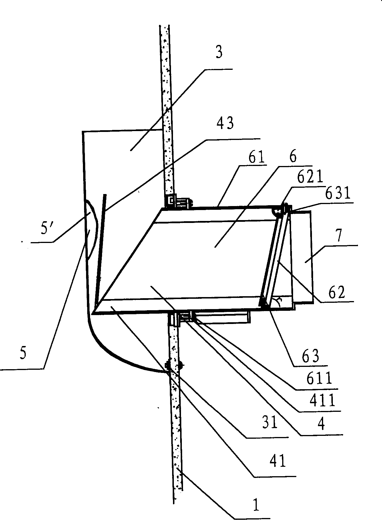
[0030] Embodiment two, see figure 2 , the figure shows a pressure-variable exhaust channel, which is based on the first embodiment, adding a one-way exhaust valve, that is, further setting the outside of the air inlet 11 of the main pipeline 1 There is a one-way exhaust valve 6, which includes a housing 61 connected to the air inlet 11 of the main pipeline 1 and the housing 41 of the diversion type check exhaust valve 4, and is fixed to the housing. The valve frame 62 and the valve plate 63 in the body 61, the rotating shaft 631 at the top of the valve plate 63 is rotatably arranged in the mounting hole 621 inside the valve frame 62; the housing 61 is tubular, The casing 61 and the main pipeline 1 are fixed on the wall outside the air inlet of the main pipeline 1 through a flange 611 . And the limiting device 5 in the first embodiment is in this embodiment figure 2 A stop protrusion 5' provided on the inner wall of the guide tube 3 shown in the figure. Moreover, the inlet...
Embodiment 3
[0033] Embodiment 3, this embodiment is based on Embodiment 1, and the diversion check exhaust valve 4 is replaced by a composite one-way exhaust valve 10, see image 3 , the figure shows the structure of the composite one-way exhaust valve 10, that is, the combined structure of the diversion check exhaust valve 4 and the one-way exhaust valve 6, the housing 61 and the The casing 41 is integrally formed to form the casing 101 , and a flange 102 fixed on the outer wall of the air inlet 11 of the main pipe 1 is provided at the waist. Another point of difference from Embodiment 1 is: the limiting device 5 is a limiting protrusion 5’’ located at the bottom of the housing 41 and the outer surface of the valve plate 43; and at the inlet end of the housing 101 A circular interface 7 connected with the exhaust pipe of the exhaust fan is further provided. This composite one-way exhaust valve will obtain a better sealing effect.
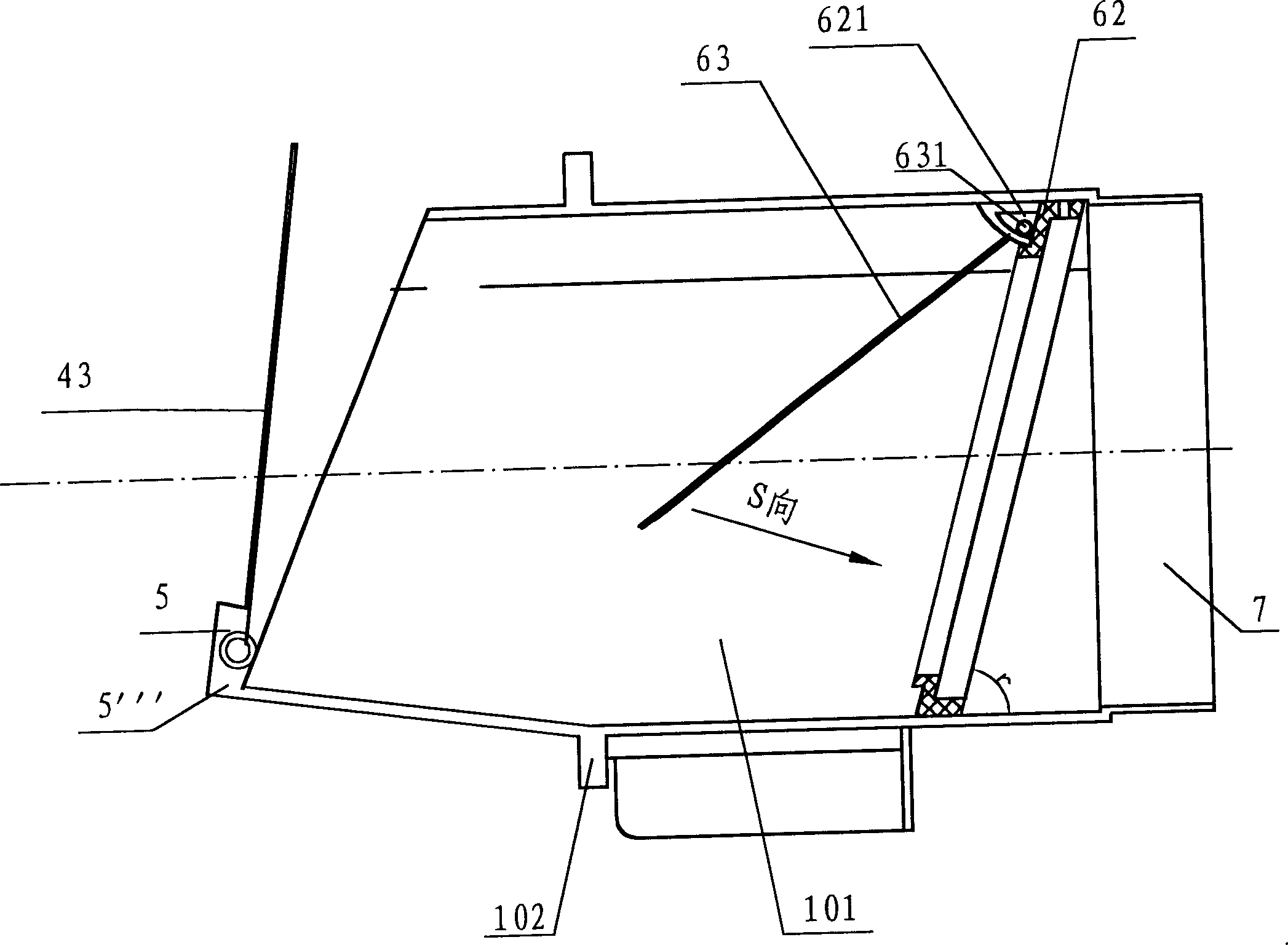
[0034] As shown in Figure 4, the figure shows the stru...
PUM
 Abstract
Description
Claims
Application Information