Automatic door latch device

A technology for automatic doors and door bodies, applied to building fastening devices, wing leaf fastening devices, buildings, etc., which can solve the problems of difficult storage of heavy objects or conical blocks, damage to the ground or floor, and scratches on the surface of the door body and other problems, to achieve the effect of reliable stop effect, not easy to break down, and high accuracy of installation

Inactive Publication Date: 2003-04-23
刘明裕
View PDF0 Cites 1 Cited by
  • Summary
  • Abstract
  • Description
  • Claims
  • Application Information

AI Technical Summary

Problems solved by technology

[0003] Press, the general traditional door body is not provided with a doorstop, when opening, people often use a weight or a conical block as a stopper, to prevent being closed suddenly by the effect of wind force, or hitting its side wall suddenly; , in use, every time you want to close the door, you need to remove the heavy object or the tapered block, and then the door can be reset and closed; moreover, the storage of the heavy object or the tapered block is not easy, easy to lose, and It is also easy to scratch the surface of the door body, so it needs to be improved
[0004] Furthermore, there is another conventional doorstop that uses a positioning rod as a stopper. It is provided with a positioning rod close to the ground on the door body, and a corresponding positioning hole must be provided on the ground or the floor. When the door body When it is opened to the position to be positioned, it is necessary to extend the positioning rod downwards with the hand, so that the function rod of the positioning rod can extend into the positioning hole to achieve the purpose of positioning; however, the setting height of the positioning rod must be very high. It is close to the ground, so in operation, people have to bend down to operate, so there is inconvenience in operation; in addition, this is commonly used, and positioning holes need to be provided on the ground or the floor, and the ground or the floor will be damaged, so there is nothing to do. Ideal

Method used


Image

  • Automatic door latch device
  • Automatic door latch device
  • Automatic door latch device

Examples


Embodiment Construction

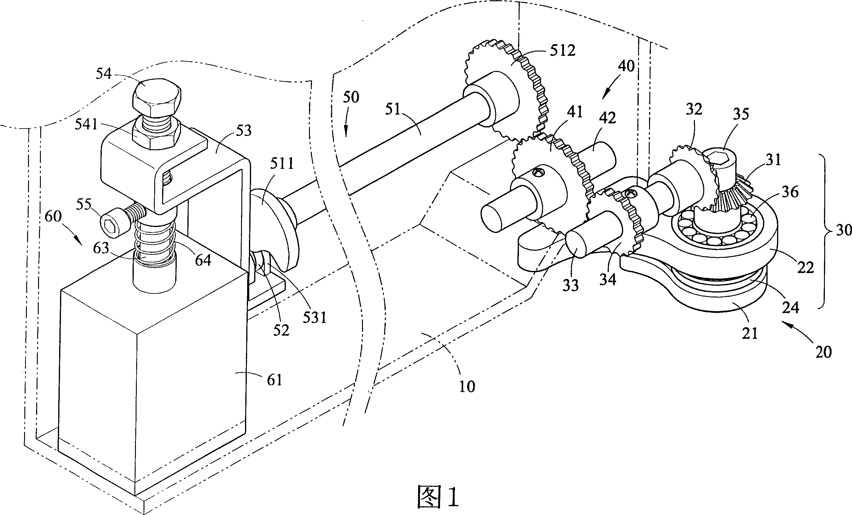
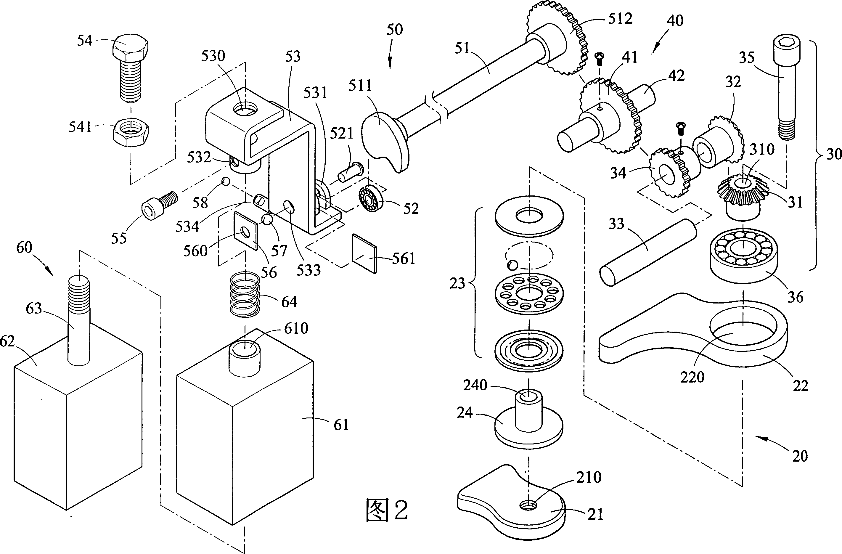
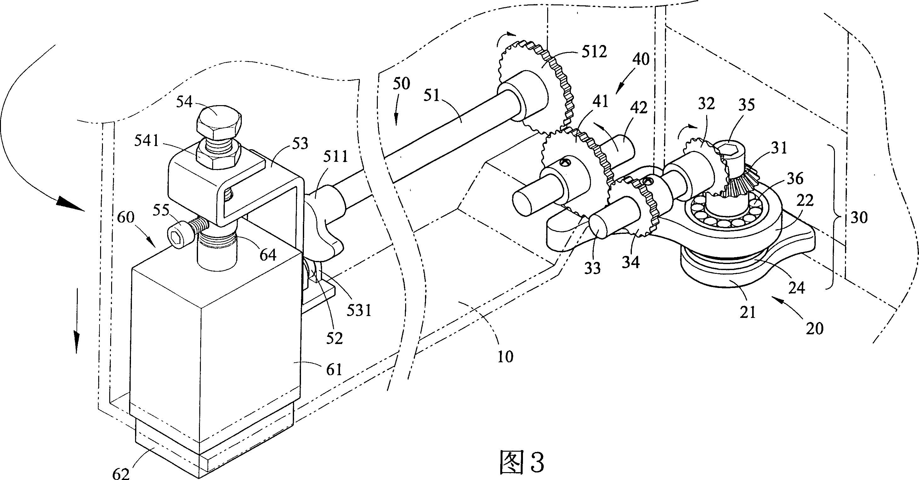
[0031] As shown in Figure 1 to Figure 3, it is the three-dimensional, three-dimensional decomposition, and schematic diagram of the action of the present invention; as shown in the figure, in a preferred embodiment, the device of the present invention can include a door body unit 10, a pivot unit 20. A driving unit 30, a transmission unit 40, a lifting unit 50, and a stopper unit 60, etc.; wherein:

[0032] The door body unit 10 is a door body pivotally arranged on the door frame;

[0033] The pivot unit 20 is composed of a lower pivot seat 21, an upper pivot seat 22, a plane bearing 23 and a pivot member 24, and is arranged on a door closer to the ground, and the plane bearing 23 is passed through the pivot. Connector 24, and located between the lower pivot seat 21 and the upper pivot seat 22;

[0034] The driving unit 30 is composed of a first bevel gear 31, a second bevel gear 32, a shaft center 33, a driving gear 34, a fixing bolt 35 and a needle bearing 36. The needle be...


PUM


Abstract

The automatic door stopping device includes a door body unit, a pivot unit, and driving unit a transmission unit, lifting unit and a stopping unit. It is characterized by that it utilizes the pivoting motion produced when the door body is opened as source of driving force, and utilizes the transmission of the pivot unit, driving unit and transmission unit to make the lifting unit produce a downward linear motion to make stopping block of stopping unit progressively downward move until the stopping block is contacted with floor to form a pressure so as to produce a stopping action, so that thedoor body unit can be positioned at a predefined position. When the door body unit is operated oppositely, the stopping action of the stopping block can be automatically eliminated.

Description

Technical field: [0001] The invention relates to an automatic door stopper, especially a door stopper suitable for a door body, and has the function of fixed-point positioning, so that the door body can be automatically opened at the set fixed-point position with the action of opening. A stop effect is generated to locate at the set opening angle. Background technique: [0002] The purpose, composition, technical means and functions of commonly used door files are listed below. Please refer to: [0003] Press, the general traditional door body is not provided with a doorstop, when opening, people often use a weight or a conical block as a stopper, to prevent being closed suddenly by the effect of wind force, or hitting its side wall suddenly; , in use, every time you want to close the door, you need to remove the heavy object or the tapered block, and then the door can be reset and closed; moreover, the storage of the heavy object or the tapered block is not easy, easy to l...

Claims


Application Information

Patent Timeline
Patent Type & Authority Applications(China)
IPC IPC(8): E05C19/02
Inventor 刘明裕
Owner 刘明裕
Why Eureka
Try Eureka