

Washing machine
A technology for washing machines and clothing, applied in the field of washing machines, can solve the problems of reducing cleaning performance and the like
- Summary
- Abstract
- Description
- Claims
- Application Information
AI Technical Summary
Problems solved by technology
Method used
Image

Examples
no. 1 example
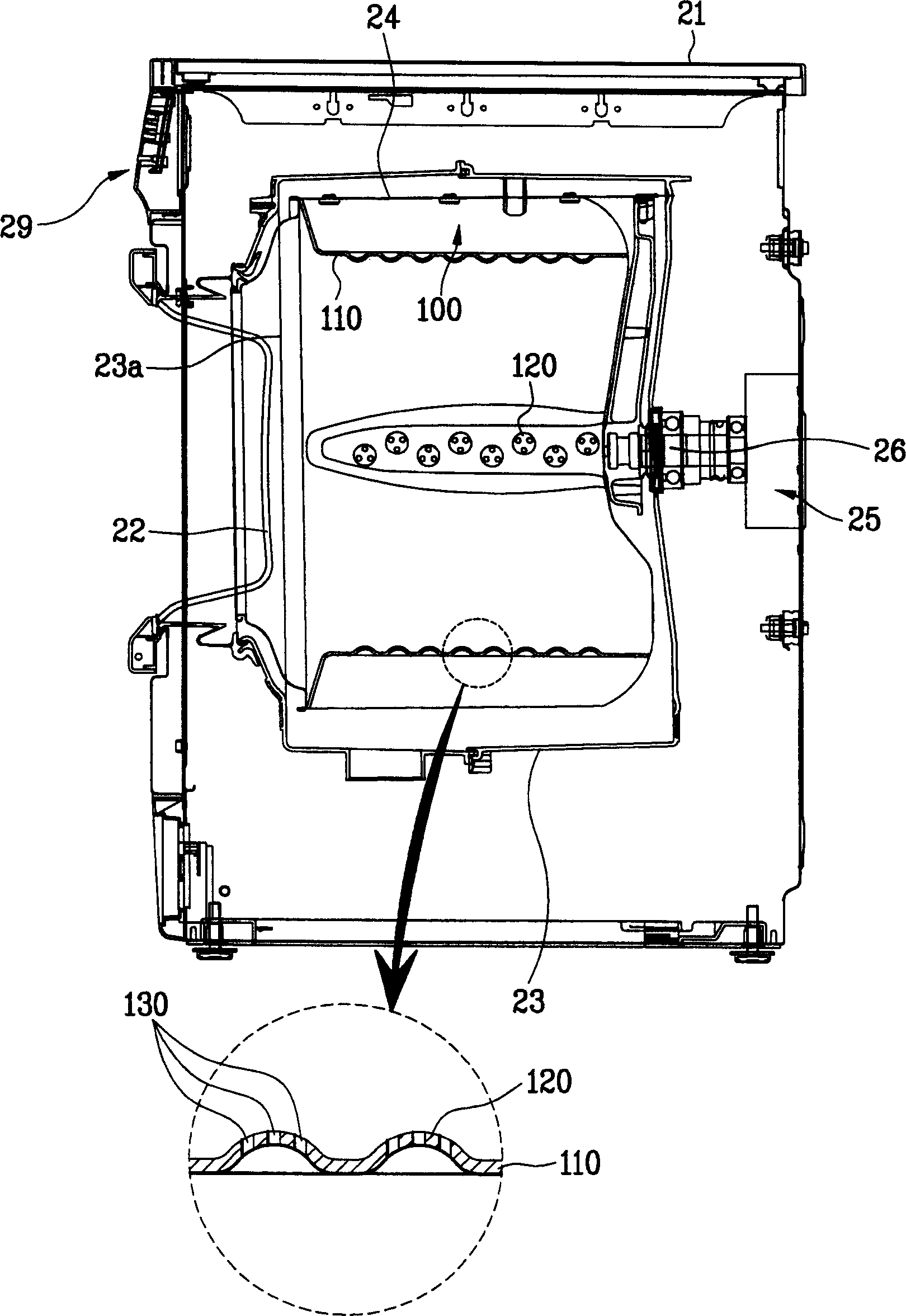
[0043] image 3 A sectional view of a drum type washing machine according to a first embodiment of the present invention is shown. image 3 An enlarged cutaway view of a portion of the riser is included. The washing machine of the first embodiment of the present invention includes a cabinet 21 with a front door 22 and an outer tub 23 inside the cabinet 21 , the outer tub 23 including an opening 23 a facing the door 22 . A rotary drum 24 is inside the outer tub 23 . The tub 23 is filled with washing water, and the drum 24 is filled with laundry. A drive part 25 (motor) behind the tub 23 is connected to the drum 24 through a drive shaft 26 . The drive member 25 (motor) generates a rotational force that rotates the drum 24 . In the first embodiment, the drum 24 is parallel to the outer tub 23 which is in turn parallel to the ground.
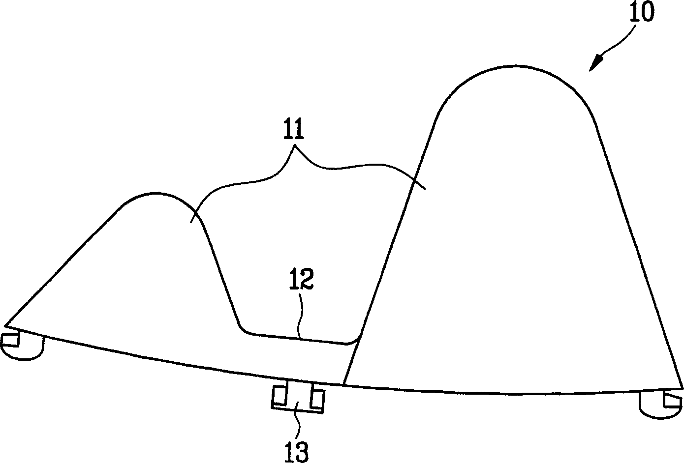
[0044] On the wall of the drum 24 there are a plurality of inwardly protruding lifters 100 extending along the axis of rotation of the drum 24 ....
no. 2 example
[0050] Figure 4 A sectional view of a tilting washing machine according to a second embodiment of the present invention is shown. Figure 4 Also included is a zoomed-in view of a portion of the lifter. Refer below Figure 4 , The washing machine of the second embodiment of the present invention is an inclined drum type washing machine. The washing machine includes a cabinet 31 with a door 22 at an inclined surface. Outer tub 33 adornment washing water in the casing. The tub 33 includes an opening 33 a facing the door 32 . The drum 34 is inside the tub 33 . A driving part 35 (motor) located behind the tub 33 is connected to the drum 34 through a driving shaft 36 . The outer tub 33 is installed with a certain inclination, so that the front portion (with the opening 33a) of the outer tub 33 is higher than the rear portion.
[0051] also refer to Figure 4 , a plurality of lifters 300 are installed on the wall of the drum 34 . These lifters, projecting inwardly towards t...
no. 3 example
[0054] Figure 5 A sectional view of a drum type washing machine according to a third embodiment of the present invention is shown. Since the drum type washing machine of the third embodiment is very similar to the washing machine of the first embodiment, the lifter 300 (which is different) will be specifically described below.
[0055] like Figure 5 As shown, a plurality of lifters 300 are mounted on the wall of the drum 24 . Preferably, each lifter 300 extends parallel to the axis of the drum 24 and protrudes from the drum wall towards the center of the drum 24 . Each lifter 300 includes a plurality of washing balls 320 protruding from the surface of the lifter 300 . The wash ball 320 functions as a friction enhancing device. The washing ball 320 is rotated in the lifter 300 by rubbing against the laundry.
[0056] Image 6 A cross-sectional view of the lifter 300 is shown. As shown, each lifter 300 includes a lifter body 310 attached to the wall of the drum 24 . A ...
PUM
 Abstract
Description
Claims
Application Information