
Fuel device and pump, injector

A fuel injection and injector technology, applied in the direction of fuel injection pump, fuel injection device, liquid fuel feeder, etc., can solve the problems of inability to supply fuel, lower fuel pump efficiency, lower fuel metering accuracy, etc., to prevent garbage and The effect of dust intrusion, improved freedom of arrangement, and elimination of arrangement space

Inactive Publication Date: 2003-04-30
HONDA MOTOR CO LTD
View PDF1 Cites 18 Cited by
  • Summary
  • Abstract
  • Description
  • Claims
  • Application Information

AI Technical Summary

Problems solved by technology

Part of the mixed steam is discharged through the return pipe, but the remaining steam remains in the fuel supply pipe and the return pipe without being discharged, and becomes an obstacle to the smooth supply of fuel, making it difficult to start the engine
In addition, when steam is supplied to the fuel pump, the efficiency of the fuel pump is reduced, and the metering accuracy of the fuel is also reduced, so that a certain amount of fuel cannot be supplied to the injector.

Method used


Image

  • Fuel device and pump, injector
  • Fuel device and pump, injector
  • Fuel device and pump, injector

Examples


Embodiment Construction

[0026] Hereinafter, embodiments of the present invention will be described in detail with reference to the drawings. The present invention is based on the premise of using a pump-injector integrated with a fuel pump and an injection nozzle for downsizing a fuel injection type fuel device, thereby achieving downsizing, eliminating the problem of arrangement space, and improving the degree of freedom of arrangement.

[0027] Figure 8 It is a schematic diagram showing an example of a pump / injector used in the present invention, and is an example in which a fuel pump including, for example, a solenoid type plunger pump is disposed in the sub tank 10 . Fuel is supplied from the fuel tank to the sub tank 10 . pump drive unit 11 such as Figure 9 As shown in a simplified example, by energizing the solenoid coil 16, the plunger 18 with the spring 17 moves up and down, and the fuel is sucked from the suction port 12 having a check valve to the fuel pump part 14, and the fuel is suck...


PUM


Abstract

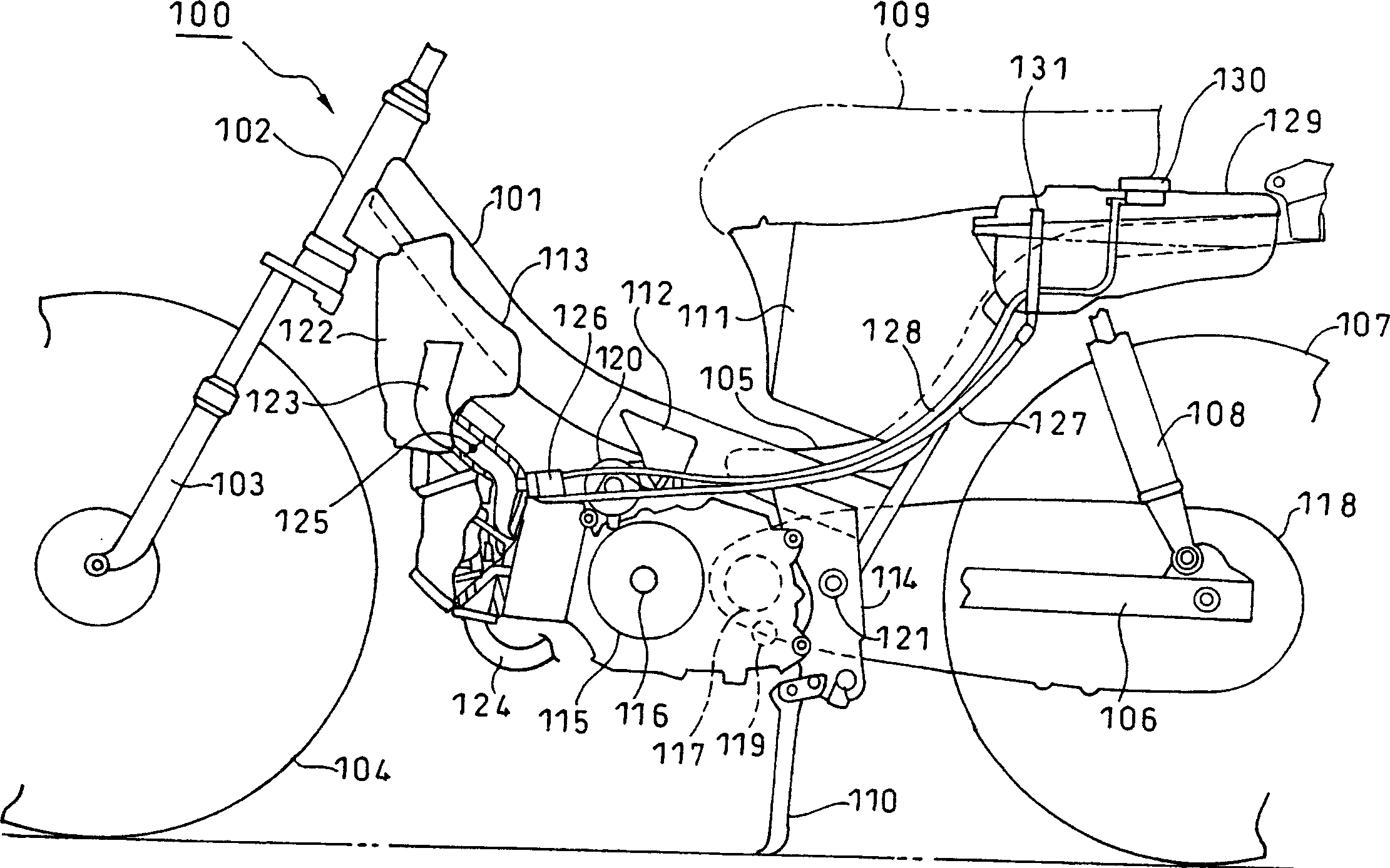
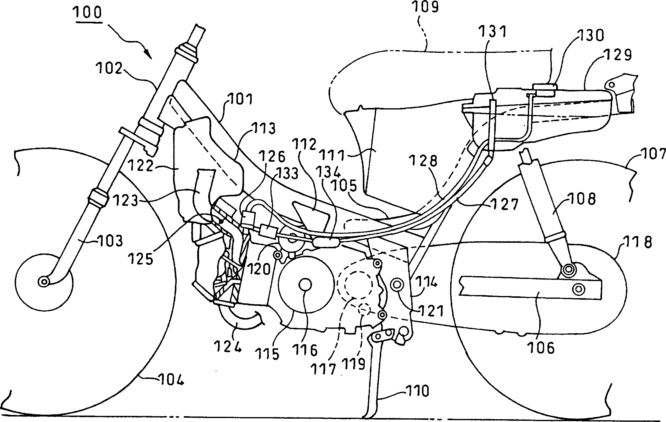
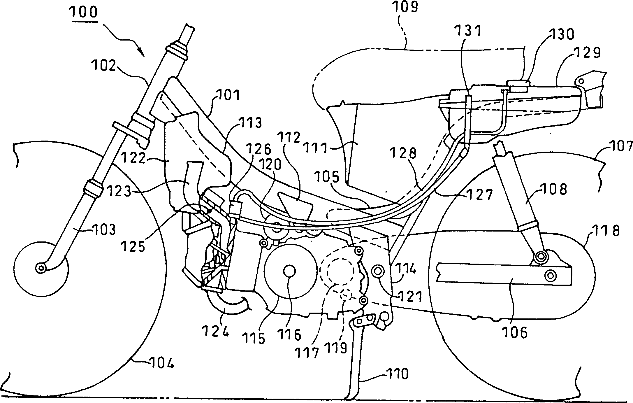
The invention provides a fuel system and a pump injector, which can eliminate a problem of an arrangement space and heighten a degree of freedom of arrangement by miniaturizing the device, and which can prevent bubbles, so-called vapor gas mixed in fuel, from staying in a fuel feed piping and a return piping. A fuel pump and an injection nozzle for fuel injection are integrated to constitute a small pump injector 126. At least one of a fuel feed piping 127 and a return piping 128 linked with the pump injector 126 is introduced in an approximately horizontal direction, so as to facilitate suction, separation and exhaust of the vapor gas mixed in the fuel. The fuel feed piping 127 and the return piping 128 may have the inside diameter for smoothly transferring the vapor gas generated in the piping through the piping by a buoyancy. A small auxiliary pump and a filter may be installed in the fuel feed piping 127. Because low pressure fuel and vapor gas pass through the fuel feed piping 127 and the return piping 128, a flexible pipe made of rubber and the like can be used for facilitating the layout.

Description

technical field [0001] The present invention relates to a fuel device and a pump / injector of a fuel injection system, and more particularly, to a fuel-containing pump that eliminates the problem of arrangement space and increases the degree of freedom of arrangement by realizing miniaturization and preventing fuel from being mixed. Bubbles and so-called steam are trapped in the fuel supply piping and return piping to improve the starting and running performance of fuel devices, pumps and injectors. Background technique [0002] Figure 11 A fuel device of a conventional fuel injection system is shown, and fuel stored in a fuel tank 1 is supplied to a fuel pump 4 through a fuel supply pipe 2 and a fuel filter 3 provided in the middle of the fuel supply pipe 2 . Fuel pressurized by the fuel pump 4 is supplied to the injector 6 through the discharge pipe 5 . At the initial stage and when the fuel is used up, the vapor present in the fuel supply pipe 2, fuel filter 3, and fuel ...

Claims


Application Information

Patent Timeline
Patent Type & Authority Applications(China)
IPC IPC(8): B60K15/03B62J35/00F02M37/00F02M37/18F02M37/20F02M49/00F02M55/00F02M55/02F02M57/02F02M59/44
CPCY02T10/123Y02T10/12
Inventor 上田稔山崎隆太郎
Owner HONDA MOTOR CO LTD
Learn More