Wall air Conditioner

A technology for wall-mounted air conditioners and air conditioners, applied in air conditioning systems, heating methods, space heating and ventilation, etc., can solve the problem of difficulty in reaching all corners of warm air or cool air evenly, and achieve uniform air conditioning. Effect

Inactive Publication Date: 2003-05-07
SANYO ELECTRIC CO LTD +1
View PDF0 Cites 6 Cited by
  • Summary
  • Abstract
  • Description
  • Claims
  • Application Information

AI Technical Summary

Problems solved by technology

[0004] But, the existing structure that is made of two horizontal valves and many vertical valves, when heating st

Method used


Image

  • Wall air Conditioner
  • Wall air Conditioner
  • Wall air Conditioner

Examples


Embodiment Construction

[0041] Invented embodiment

[0042] The embodiments of the present invention will be described below based on the drawings.

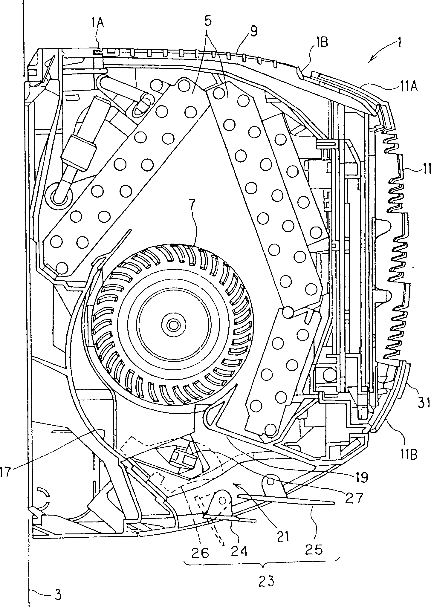
[0043] figure 1 It is a longitudinal cross-sectional view showing an embodiment of the wall-mounted air conditioner of the present invention. 1 denotes the main body of the air conditioner, and the main body 1 is installed on the wall 3. An indoor heat exchanger 5 and a cross flow ventilation fan 7 are provided in the main body 1.

[0044] The upper suction port 9 is made into a grid shape and is formed on the upper part 1A of the main body 1. In the state of hinged around the fulcrum omitted in the figure, the suction grid 11 is installed with the upper end 11A on the front edge of the upper part 1A On the part 1B, the lower end 11B can be opened from the front of the air conditioner body 1.

[0045] Inside the suction grid 11, a suction filter 13 with a filter element which can be lifted and lowered freely is installed.

[0046] In the lower part of the...


PUM


Abstract

The problem to be solved by the present invention is to uniformly condition an air-conditioned room by having warm air or cold air to reaching every corner of the air-conditioned room. The solution of the present invention is that in a wall-mounted air conditioner, an air-conditioner body 1 with an air flow discharge port comprising air flow orienting plate means 23. The air flow orienting plate means comprises upper side horizontal air gate plates 25A and 25B and a lower side horizontal air gate plate 24, wherein the upper side horizontal air gate plates 25A and 25B are arranged in an upper longitudinal axis direction within the air discharge port, while the single piece of horizontal air gate plate 24 is arranged to extend in a lower longitudinal axis direction. The upper side horizontal air gate plates 25A and 25B are allowed to rotate in opposite directions within an arbitrary range of longitudinal arrangement, while the lower side horizontal air gate plate 24 is allowed to rotate within a range smaller than the rotation range of the upper side air gate plates.

Description

Technical field [0001] The invention relates to a wall-mounted air conditioner equipped with a wind direction changing plate on an air outlet of an air conditioner body. Background technique [0002] As is well known, a wall-mounted air conditioner generally has a wind direction changing plate in an air outlet surrounded by a scroll portion and a tongue portion of the air conditioner body. The structure of this wall-mounted air conditioner is as follows: two horizontal valves and multiple vertical valves are used to form a wind direction changing plate. By changing the directions of these horizontal and vertical valves, the direction of the air flow from the air ejection outlet can be controlled. [0003] For example, in the cooling state, control is performed to eject the airflow approximately horizontally to increase the reach of the airflow, and in the heating state, control is performed to eject the airflow approximately vertically downward to form an airflow that flows along...

Claims


Application Information

Patent Timeline
IPC IPC(8): F24F13/15F24F3/06F24F13/30
CPCF24F1/0057F24F13/14
Inventor 松本公一进士干泰
Owner SANYO ELECTRIC CO LTD
Why Eureka
Try Eureka