
Electricity bill control device and recording medium therefor

A technology for managing devices and electricity bills, applied to circuit devices, electrical components, AC network circuits, etc., can solve problems such as increased costs, longer recovery years for energy-saving costs, and difficulty in increasing user investment

Inactive Publication Date: 2003-05-07
ZENSHIN DENRYOKU ENG
View PDF1 Cites 13 Cited by
  • Summary
  • Abstract
  • Description
  • Claims
  • Application Information

AI Technical Summary

Problems solved by technology

However, when the working conditions of the load are different before and after construction, it is difficult to accurately verify the energy-saving effect. Not only must long-term measurement be carried out, but the cost on it will also increase.
Therefore, judging from the amount of money cut due to energy saving, the recovery period of energy saving costs will be longer, so it is difficult for users to increase their investment in this

Method used

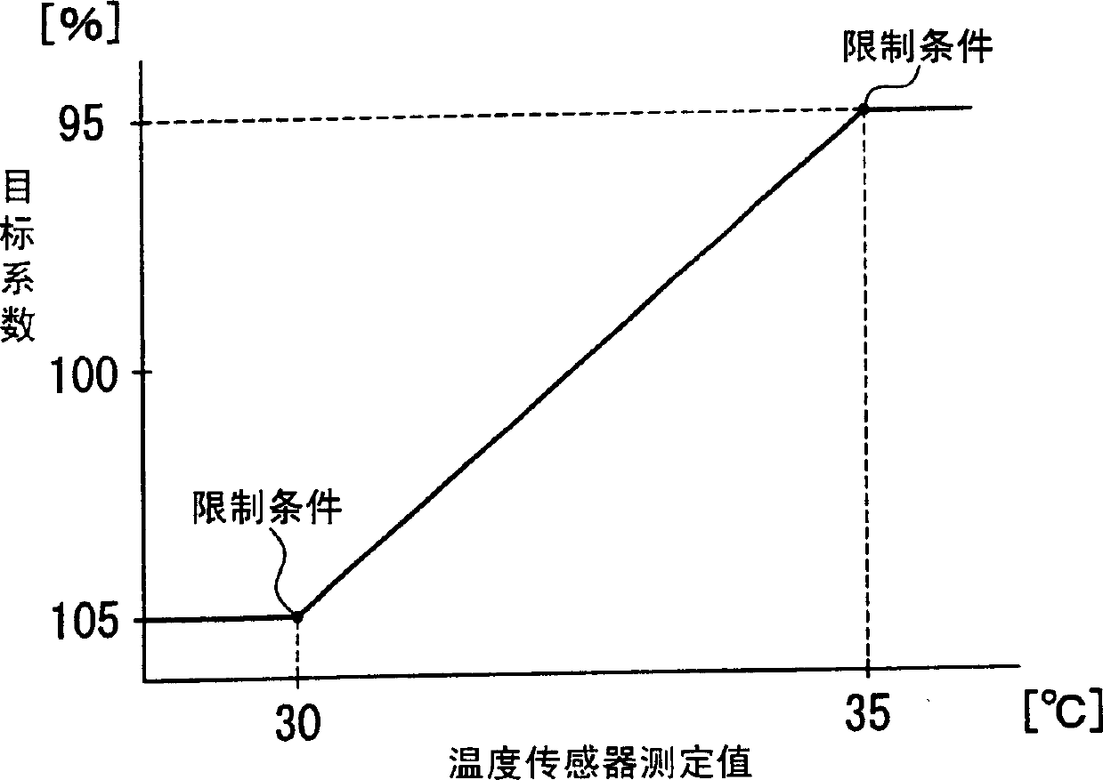
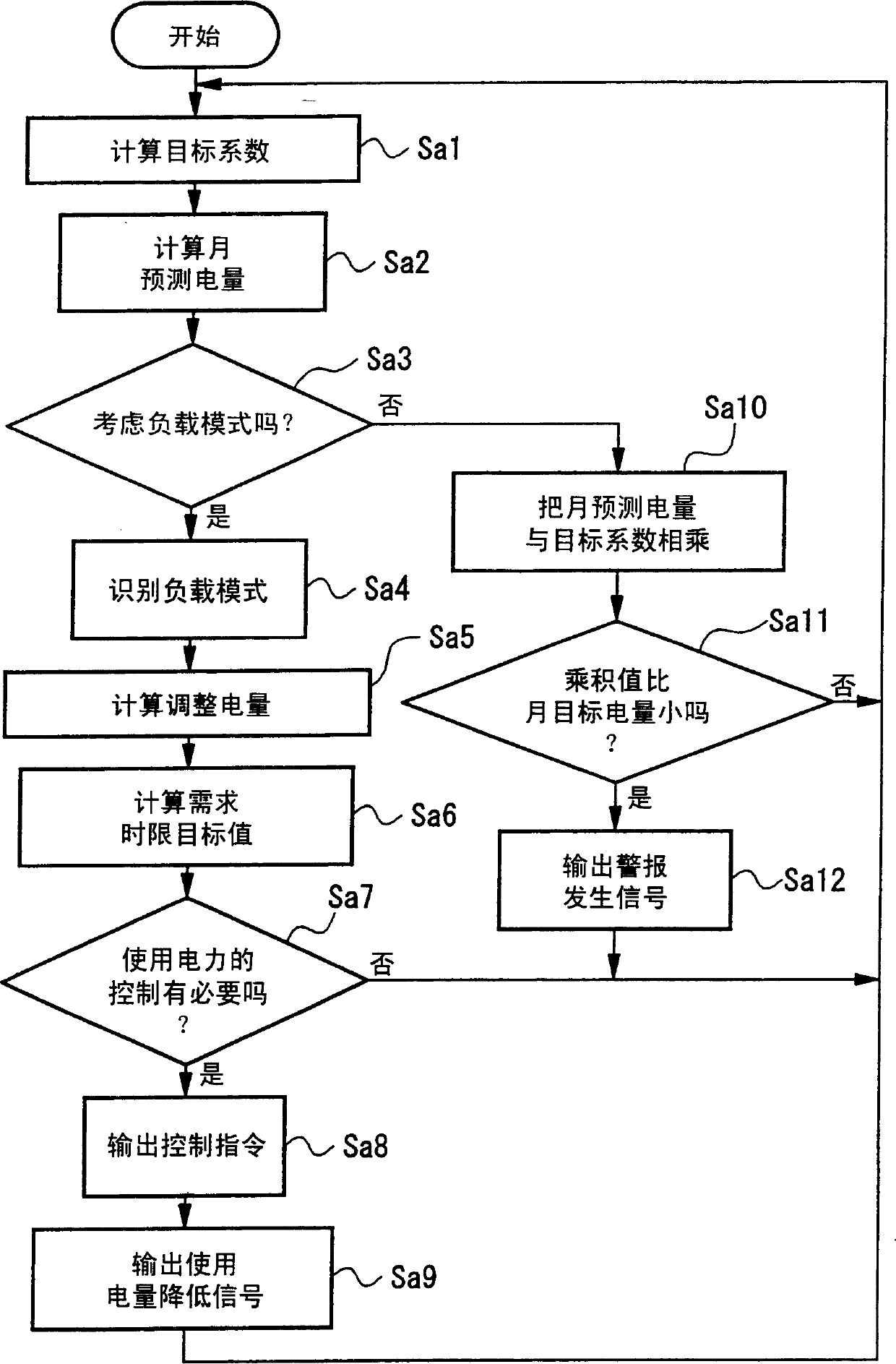

Image

  • Electricity bill control device and recording medium therefor
  • Electricity bill control device and recording medium therefor
  • Electricity bill control device and recording medium therefor

Examples


Embodiment Construction

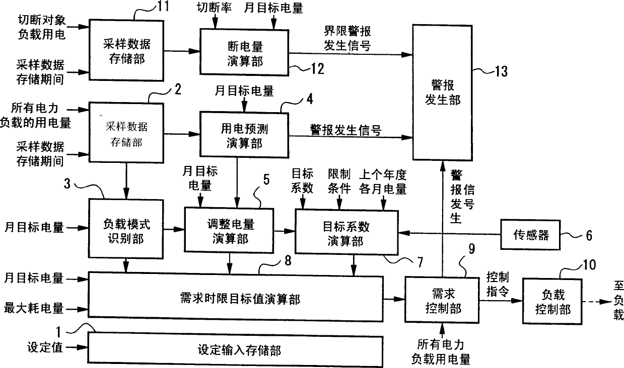
[0029]Hereinafter, an embodiment of the electricity charge management device of the present invention will be described with reference to the accompanying drawings. FIG. 1 is a diagram showing the configuration of an electricity bill management device according to this embodiment. In this figure, 1 is a setting input storage unit, which sets and stores various parameters set by the user as shown below.

[0030] In addition, in the description of the following examples including this example, the given period as the collection period of the electricity fee is assumed to be one month from the beginning of the month to the end of the month, and the unit time divided into the given period is taken as the demand time limit. The required time limit will be explained separately.

[0031] (1) Monthly target power consumption

[0032] It is the target value of the electricity (Kwh) used from the beginning of the month to the end of the month. It is set for all electric loads install...


PUM


Abstract

In addition to a dissociation ratio being calculated with a load pattern recognition unit 3 based on sample data of the amount of electrical power in an electrical power load accumulated in a sample data accumulation unit 2, adjusted electrical power and a target coefficient are calculated with an adjusted electrical power arithmetic processing unit 5 and a target coefficient arithmetic processing unit 7. In addition, a demand period target value arithmetic processing unit 8 calculates a target value of the amount of electrical power used by an electrical power load for each demand period based on the dissociation ratio, adjusted electrical power and target coefficient. The amount of electrical power used by the electrical power load is then controlled by a demand control unit 9 and load control unit 10 based on this target value.

Description

technical field [0001] The present invention relates to an electricity charge management device and a recording medium thereof for managing electricity charges collected according to the amount of electricity used. Background technique [0002] Conventionally, as a method of managing power consumption by power consumers, it is common to use a demand controller that suppresses peaks in power demand. The purpose of the so-called demand controller is to set a target value for the maximum value of the average power usage at each given time used by the power demander, and to manage or control the load so as not to exceed the target. Generally, the average power consumption of 30 minutes is set as the target value. Therefore, in almost all buildings, the period of alarm notification from the demand controller or power control is concentrated in summer. Therefore, when the user cuts power or CO 2 Electricity (or CO 2 ) is less, and the degree of satisfaction is not high in term...

Claims


Application Information

Patent Timeline
IPC IPC(8): G06Q10/00G06Q50/00G06Q50/06G06Q50/10H02J3/00
CPCH02J2003/003Y04S10/54H02J3/00H02J3/003Y04S10/50G06Q50/06
Inventor 桝田吉信佐佐木让
Owner ZENSHIN DENRYOKU ENG
Learn More