Needle cloth-feeding sewing machine

A sewing machine and cloth feeding technology, applied in the direction of cloth feeding mechanism, sewing machine components, sewing equipment, etc., can solve the problems of wear and deformation of the needle bar 7, deformation of the needle bar shaking table 5, etc.

Inactive Publication Date: 2003-05-14
JUKI CORP
View PDF0 Cites 4 Cited by
  • Summary
  • Abstract
  • Description
  • Claims
  • Application Information

AI Technical Summary

Problems solved by technology

[0008] However, since the restricting part 90 is fixed on the needle bar rocking table 5 with screws, the needle bar rocking table 5 will be slightly deformed when tightening with screws due to the existence of a gap between the restricting part 90 and the needle bar rocking table 5.
Although the needle bar 7 is supported by two bearings arranged up and down on the needle bar rocking table 5, the above-mentioned non-concentricity of the upper and lower bearings (centers of the upper and lower bearings are shifted) occurs due to the deformation of the needle bar rocking table 5 as described above. As a result, the needle bar 7 is twisted, resulting in wear and deformation of the needle bar 7

Method used


Image

  • Needle cloth-feeding sewing machine
  • Needle cloth-feeding sewing machine
  • Needle cloth-feeding sewing machine

Examples


Embodiment Construction

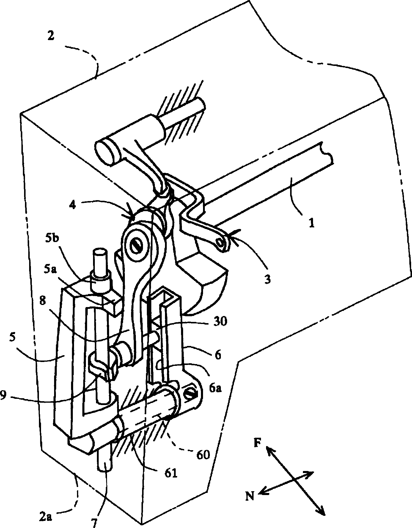
[0033] Hereinafter, an embodiment of the needle-feed sewing machine of the present invention will be described. in figure 1 Among them, the sewing machine head 2 has an upper shaft 1 that is connected to a motor (not shown) and rotatably supported, and is provided on the left end of the upper shaft 1 (the front end side of the sewing machine head 2) Thread take-up lever 3 and needle bar up and down mechanism 4. In the head 2a of the front end of the sewing machine head 2, a swing shaft (support shaft) 60 that is rotatable parallel to the upper shaft 1 is supported by a bearing 61 fixed to the frame. A needle bar rocking table 5 is fixed to one end of the rocking shaft, and a slider guide table 6 is fixed to the other end. A guide groove portion 6a is formed on the slider guide base 6.

[0034]A needle bar 7 that can move up and down is supported on the needle bar rocking table 5, and the slider guide table 6 is assembled so that the shaft center of the needle bar 7 coincides with...


PUM


Abstract

A needle feeding sewing machine has a feed dog 23 operatively connected to a vertical feed shaft 12 and a horizontal feed shaft 17 and making four-way feeding movements; a needle feed shaft 24 causing the needle- bar oscillating stand to oscillate in cloth feed direction; and switching means 27, 28 and 28a for switching between the needle feed and the low feed by changing the connection between the needle feed shaft and the horizontal feed shaft. A first engagement member 5b is provided on the needle-bar oscillating stand 5, and a first control member 33 is provided for controlling the movement of the engagement member in the cloth feed direction when the needle feed is not working. The needle feeding sewing machine reduces the backlash of a needle-bar oscillating stand during a low feed, and capable of supplying stable stitches without sewing errors such as skip stitches, nor causing deformation of the needle-bar oscillating stand.

Description

Technical field [0001] The present invention relates to a needle-feed sewing machine that feeds cloth by shaking the needle of the sewing machine in the cloth-feeding direction. Background technique [0002] As the previous needle feed sewing machine, such as Figure 14 Shown is the sewing machine disclosed in Patent No. 2682346. in Figure 14 In the sewing machine shown, there is a needle feed mechanism (needle bar rocking table 80, needle bar rocking jib 81, needle feed shaft 24) that makes the needle bar 7 oscillate around the rotating shaft 80A as the needle feed The horizontal feed shaft 17 of the drive source, the needle bar rocking arm 82 fixed to the horizontal feed shaft 17, and the rocking of the needle bar rocking arm 82 are transmitted to the connecting member 83 of the needle feed shaft 24 through the above The driving of the horizontal feeding shaft 17 causes the needle bar 7 to swing in the feeding direction. [0003] In addition, there is known a mechanism that st...

Claims


Application Information

Patent Timeline
Patent Type & Authority Applications(China)
IPC IPC(8): D05B27/20D05B27/02
Inventor 伊藤等
Owner JUKI CORP
Why Eureka
Try Eureka