Clip

A technology for clips and mounting components, applied in the direction of friction-clamped detachable fasteners, thin-plate connections, snap-action fasteners, etc., which can solve the problem of lack of gripping parts and easy removal of central components from clips, that is, dashboards , Difficult to remove the clip from the center assembly, etc.

Inactive Publication Date: 2003-05-14
NIFCO INC
View PDF2 Cites 15 Cited by
  • Summary
  • Abstract
  • Description
  • Claims
  • Application Information

AI Technical Summary

Problems solved by technology

[0004] In this way, in the clip in the prior art, since a pair of coupling pieces are gradually narrowed in the direction of pulling out the rib of the mounted member, a force to remove it from the instrument panel acts on the center assembly (mounted member). , the center assembly is easily detached from the clip, i.e. the dashboard, due to the weak holding force of the clip
[0005] Also, to remove the center assembly and clip from the dashboard, since the center assembly is easy to remove from the clip, the clip tends to stay in the dashboard, and it is difficult to remove the clip from the center assembly due to the lack of a grip on the clip

Method used


Image

  • Clip
  • Clip
  • Clip

Examples


Embodiment Construction

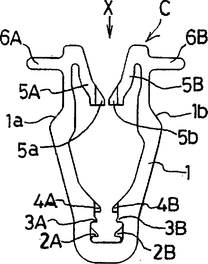
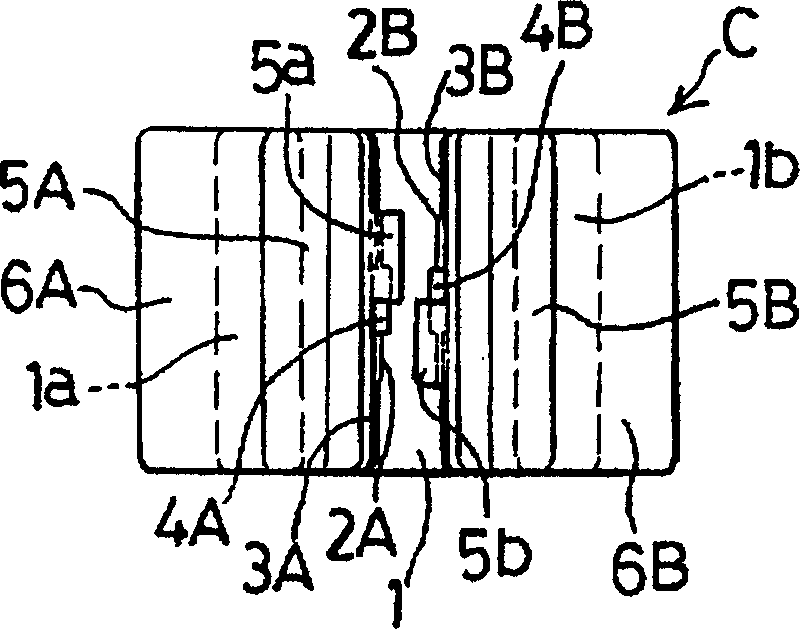
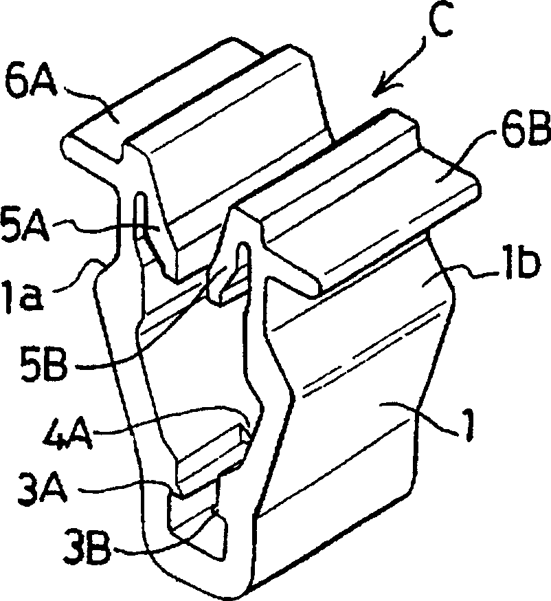
[0015] figure 1 It is a front view of a clip as an embodiment of the present invention; figure 2 yes figure 1 Plan view of the clip shown; image 3 yes figure 1 Perspective view of the clip shown; Figure 4 will be figure 1 Clip shown half-sectioned with image 3 Stereoscopic view of the same state.

[0016] In the above-mentioned figures, the clip C formed of synthetic resin is constituted by a U-shaped clip body 1 with an insertion terminal portion ( figure 1 Two pairs of clamping pieces 2A, 2B, 3A, 3B, which are set at the lower end portion of the clip body 1 and clamp the front end portion of the rib 12 from both sides with the tip portion, are inserted into the terminal portion of the rib 12 at the inside of the clip body 1, But facing the insertion start end side of the rib 12 ( figure 1 A pair of front-end coupling pieces 4A, 4B that protrude into the front-end coupling hole 12a of the rib 12 from both sides) are arranged on the upper side of the middle of the ...


PUM


Abstract

A clip is attached to a member or center cluster for detachably attaching the member to an attaching member or instrument panel. The clip is provided with a pair of engaging members projecting with an inclination so that a distance therebetween is narrowed toward the inserting direction of a rib of the center cluster, and engaging portions of the engaging members engage an engagement hole of the rib.

Description

technical field [0001] The present invention relates to, for example, a clip for detachably mounting a center assembly as a mounted member on a vehicle dashboard as a mounting member. Background technique [0002] As the above-mentioned clip, it is detachably attached to the mounting member, and the mounting member is detachably mounted to the structure of the mounted member, such as in Japanese Patent Application Laid-Open No. 10-54411 and Japanese Patent Laid-Open No. 2000-249117. somewhat public. [0003] In the clip disclosed in Japanese Patent Application Laid-Open No. 10-54411 or Japanese Patent Laid-Open No. 2000-249117, the clip is inserted from the insertion end side of the rib of the mounted member to be inserted, that is, toward the direction opposite to the insertion direction of the rib (pull out). Going direction) a pair of coupling pieces in which the coupling portion and the coupling portion of the rib are combined are provided in a inclined and protruding m...

Claims


Application Information

Patent Timeline
Patent Type & Authority Applications(China)
IPC IPC(8): F16B19/00F16B2/20F16B5/06F16B21/07
CPCF16B21/075Y10S411/913B60K2350/943B60K2350/925F16B5/06B60K2370/774B60K2370/87Y10T24/30Y10T24/302Y10T24/304Y10T24/307Y10T24/309F16B2/20
Inventor 小川敦司
Owner NIFCO INC
Why Eureka
Try Eureka