Supercharge Your Innovation With Domain-Expert AI Agents!

Manufacture of electric connector

A manufacturing method and technology of electrical connectors, applied in the direction of contact manufacturing, etc., can solve the problem that the terminal contact part 703 and the outer conductor 704 are not easy to be positioned accurately, and achieve the effect of reliable holding force

Inactive Publication Date: 2003-05-14
FOXCONN (KUNSHAN) COMPUTER CONNECTOR CO LTD +1
View PDF1 Cites 1 Cited by
  • Summary
  • Abstract
  • Description
  • Claims
  • Application Information

AI Technical Summary

Problems solved by technology

[0003] However, when the size of the above-mentioned electrical connector 700 is required to be further reduced, when the insulating body 701 is integrally formed on the terminal contact portion 703 and the outer conductor 704 to form an electrical connector, the distance between the terminal contact portion 703 and the outer conductor 704 is not easy to be precise. position

Method used


Image

  • Manufacture of electric connector
  • Manufacture of electric connector
  • Manufacture of electric connector

Examples


Embodiment Construction

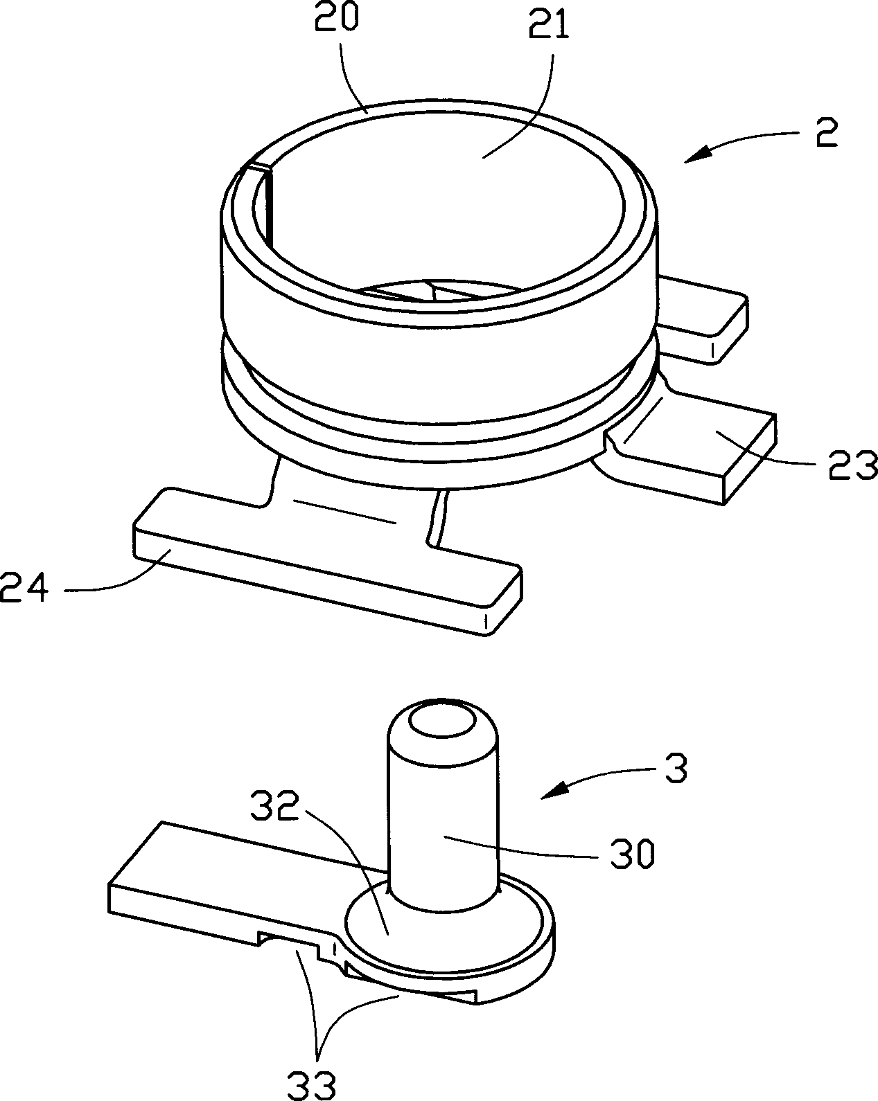
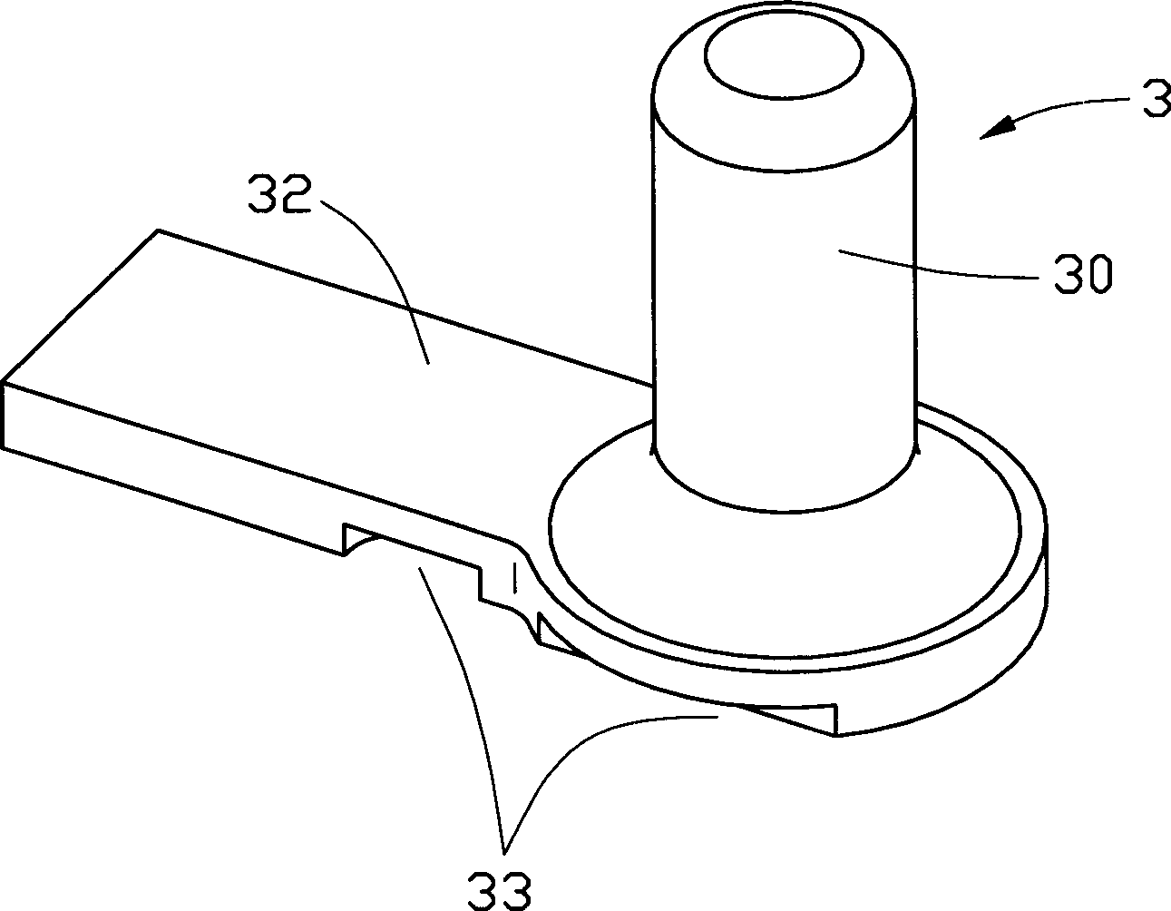
[0015] Please refer to figure 1 , figure 2 , Figure 5 and Figure 6 As shown, the electrical connector 100 manufactured by the present invention includes a metal shell 2 , a central terminal 3 and an insulating body 6 , wherein the metal shell 2 and the central terminal 3 are integrally formed in the insulating body 6 . The metal shell 2 includes a ring body 20 , a pair of welding feet 24 extending outward from the bottom side of the ring body 20 and a connecting portion 23 , and the ring body 20 is surrounded by a receiving portion 21 . The central terminal 3 includes a base portion 32 and a terminal contact portion 30 extending vertically upward along the base portion 32 and accommodated in the receiving portion 21 of the ring body 2 . In addition, several indentations 33 are provided on the base portion 32 to enhance the holding force between the insulating body 6 and the central terminal 3 .

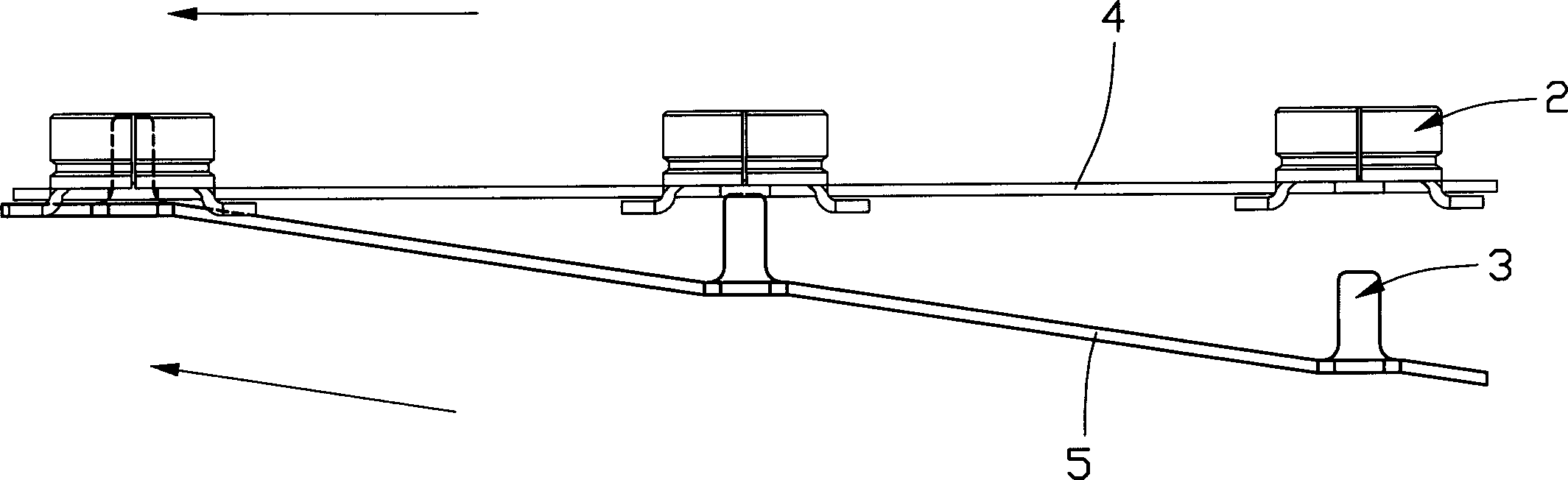
[0016] Such as image 3 , Figure 4 and Figure 7 As shown, the manufa...


PUM


Abstract

A manufacture process of electric connector includes punching metal casing and central terminal in the first and the second material sheets separately; placing the first material sheet over the second material sheet and in certain angle and corresponding the metal casing in the first material sheet and the central terminal in the second material sheet one by one; shifting the two material sheets synchronously to make the contact part of the central terminal in the center of the metal casing; and final forming the insulating body integral to fix the central terminal and the metal casing.

Description

【Technical field】 [0001] The invention relates to a method for manufacturing an electrical connector, in particular to a method for manufacturing a miniature radio frequency electrical connector. 【Background technique】 [0002] As mobile phones, PDAs and other products become smaller and smaller, more and more miniature electrical connectors are applied to these products. These connectors work in a high-frequency environment and their size is usually small. Such as Figure 8 The shown U.S. Patent No. 5,466,160 discloses a miniature electrical connector 700, including an insulating body 701, a terminal contact portion 703, an outer conductor 704, a terminal 705 electrically connected to the terminal contact portion 703, and an outer conductor 704 The electrically connected ground terminal 706 , wherein the insulating body 701 is surrounded by a receiving space 702 . [0003] However, when the size of the above-mentioned electrical connector 700 is required to be further redu...

Claims


Application Information

Patent Timeline
Patent Type & Authority Applications(China)
IPC IPC(8): H01R43/16
Inventor 吴荣发
Owner FOXCONN (KUNSHAN) COMPUTER CONNECTOR CO LTD
Features
  • R&D
  • Intellectual Property
  • Life Sciences
  • Materials
  • Tech Scout
  • Unparalleled Data Quality
  • Higher Quality Content
  • 60% Fewer Hallucinations
Learn More