
Rotary clamp tool

A technology of fixtures and rotating parts, which is applied in the field of rotating fixtures, can solve the problems of inaccurately guiding the clamping rods, etc., and achieve the effects of reducing height, reducing rotation stroke, and increasing service life

Inactive Publication Date: 2003-05-21
KOSMEK LTD (JP)
View PDF1 Cites 15 Cited by
  • Summary
  • Abstract
  • Description
  • Claims
  • Application Information

AI Technical Summary

Problems solved by technology

Therefore, when the clamp rod is driven for clamping, this assembly gap makes the clamp rod tilt, although the tilt is small, it does not lead to the clamp rod with good accuracy.

Method used


Image

  • Rotary clamp tool
  • Rotary clamp tool
  • Rotary clamp tool

Examples


no. 1 example 1

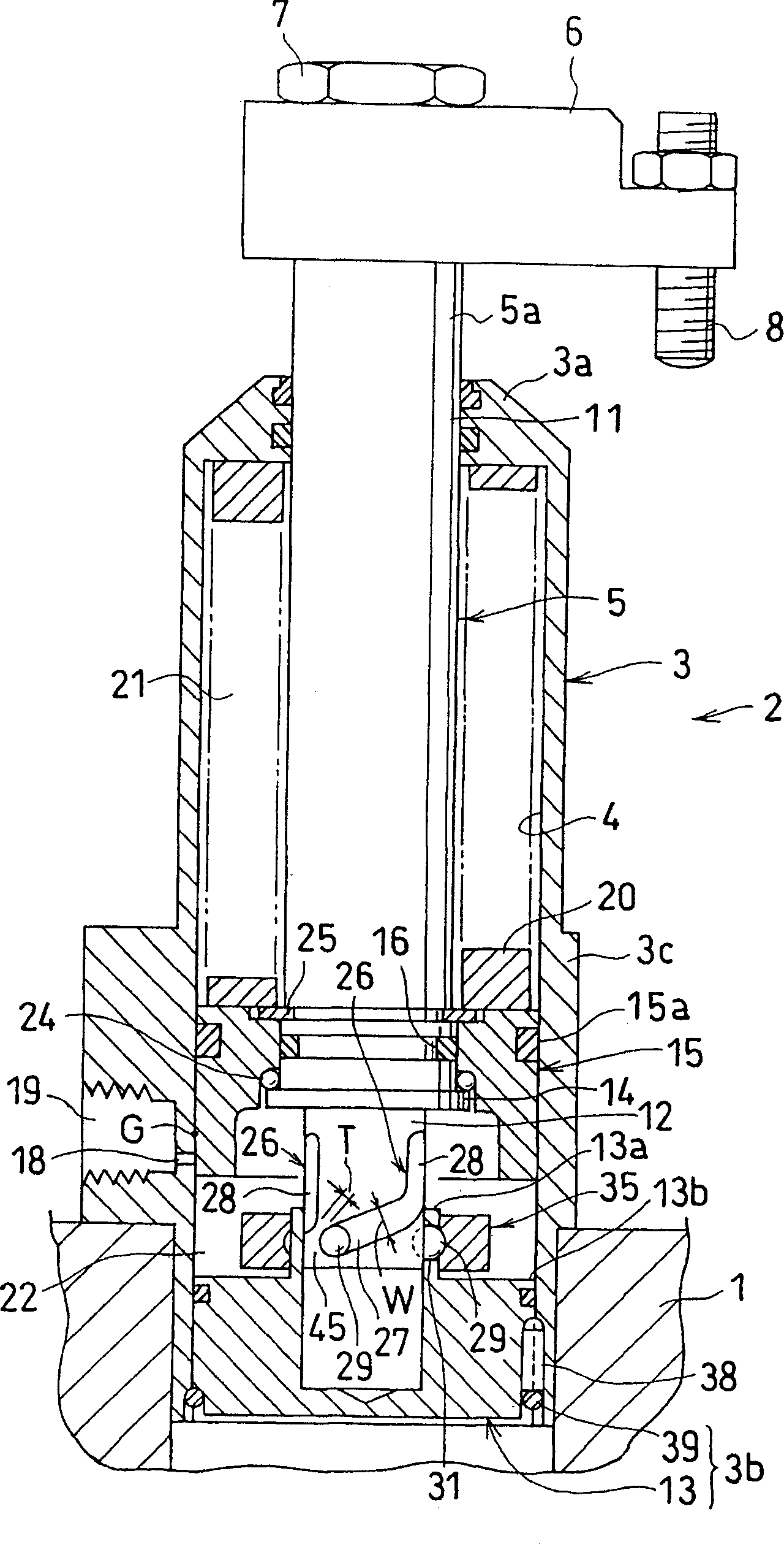
[0088] As in the first embodiment, the outer diameter of the lower sliding portion 12 is set smaller than that of the upper sliding portion 11 . In this way, the lead of the helical rotation groove is shortened, thereby reducing the rotation stroke of the clamping rod 5 .

[0089] Figure 11 A third embodiment of the present invention is shown. Figure 11 is a partial cross-sectional elevation view of the rotating fixture, which is similar to Figure 7 .

[0090] Figure 11 The third embodiment of Figure 7 The structures shown differ only in the following respects.

[0091] omitted Figure 7 Sleeve 35 is shown. The packing 32 prevents the engagement ball 29 supported by the inner wall 13 a of the support cylinder 13 from coming off.

[0092] Figure 12 Showing a first variant of the third embodiment, the figure is similar to Figure 11 .

[0093] Figure 12 The first variant of is different from Figure 11 The structure shown is in the following respects.

[009...


PUM


Abstract

The invention relates to a rotary clamp. A housing (3) has an upper end wall (3a) which supports an upper slide portion (11) of a clamp rod (5) vertically movably. The housing (3) has a lower end wall (3b), a support cylinder (13) of which supports a lower slide portion (12) of the rod (5) vertically movably. The rod (5) is provided with an input portion (14) between the upper slide portion (11) and the lower slide portion (12). A clamp spring (20) connected to the input portion (14) drives the rod (5) downwards for clamping. The lower slide portion (12) has an outer periphery provided with a helical rotary groove (27) and a straight groove (28) which is in upward continuity with the rotary groove (27). A ball (29) engages with the rotary groove (27) and the straight groove (28). The ball (29) is supported by an inner wall (13a) of the support cylinder (13).

Description

technical field [0001] This invention relates to clamps of the type that rotate the clamp lever. Background technique [0002] There are known such jigs of the conventional art, which are constructed in the following manner, for example as disclosed in US Patent No. 5,820,118. [0003] The clamping rod is inserted into the housing, and the upper wall of the housing rotatably supports the half-height portion of the clamping rod. The clamp bar has a lower portion with a piston vertically movably supported by the barrel portion of the housing. [0004] Conventional techniques have the following problems. [0005] A fitting gap is formed between the outer peripheral surface of the piston formed on the lower portion of the clamp rod and the barrel portion of the housing. Thus, when the clamping rod is driven for clamping, this assembly gap tilts the clamping rod, which, although slight, does not allow the clamping rod to be guided with good accuracy. Contents of the inventio...

Claims


Application Information

Patent Timeline
Patent Type & Authority Applications(China)
IPC IPC(8): B23Q3/06B25B5/06
CPCB25B5/062B23Q3/06
Inventor 米泽庆多朗横田英明春名阳介
Owner KOSMEK LTD (JP)
Features
  • Generate Ideas
  • Intellectual Property
  • Life Sciences
  • Materials
  • Tech Scout
  • Unparalleled Data Quality
  • Higher Quality Content
  • 60% Fewer Hallucinations
Learn More