Snap-in connection for pumping plunger sliding shoes

A technology of plunger and pump pressure, applied in the direction of components, pumps, pump components, etc. of pumping devices used for elastic fluids, can solve problems such as difficult, difficult to assemble, and difficult

Inactive Publication Date: 2003-05-28
STANADYNE AUTOMOTIVE
View PDF0 Cites 2 Cited by
  • Summary
  • Abstract
  • Description
  • Claims
  • Application Information

AI Technical Summary

Problems solved by technology

The rotatable connection between the plunger and the sliding shoe presents some difficulties in manufacture and assembly
Often it is difficult to find a sliding shoe material that has the proper wear resistance and still is malleable enough to allow the sliding shoe to be made around the end of the plunger and gr

Method used


Image

  • Snap-in connection for pumping plunger sliding shoes
  • Snap-in connection for pumping plunger sliding shoes
  • Snap-in connection for pumping plunger sliding shoes

Examples


Embodiment Construction

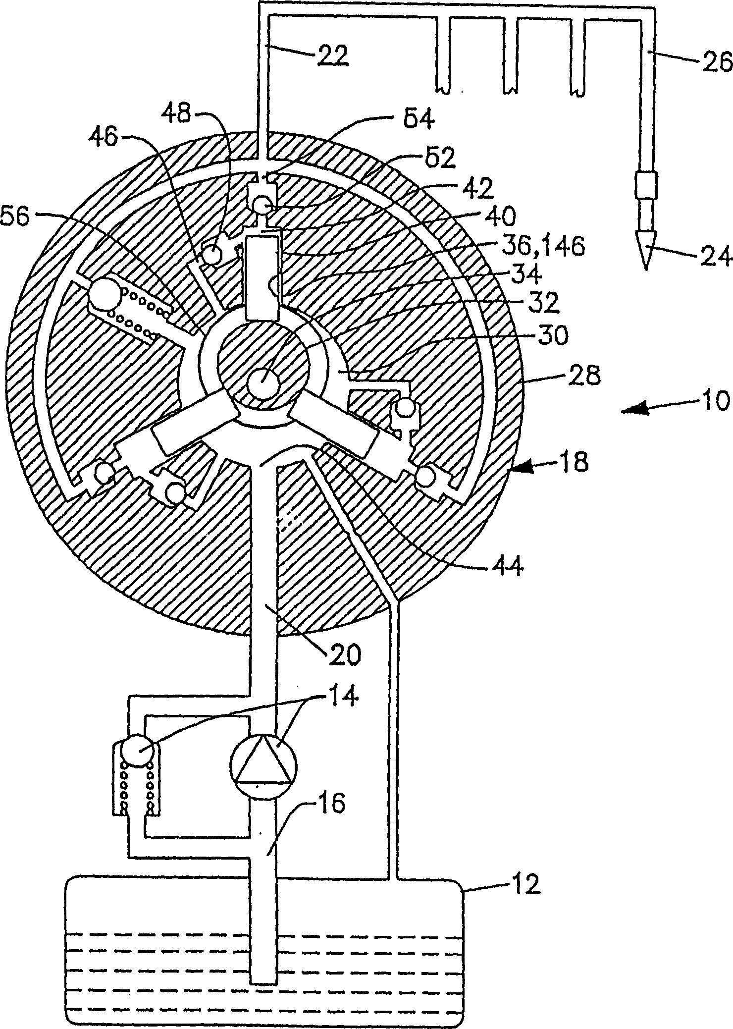
[0044] figure 1 is a schematic illustration of a fuel injection system 10 comprising a fuel tank 12 and a feed pump 14 fitted with a low pressure regulator for delivering fuel via a low pressure fuel line or suction line 16 to an internally driven feed pump 18 . Fuel from feed pump 14 enters feed pump 18 through an inlet port or passage 20 where the fuel builds up pressure. High pressure fuel is discharged into an external manifold 22 for delivery to a plurality of fuel injectors 24 each fueled by a fuel injector manifold 26 . Alternatively, the pump 18 may directly supply oil to the branch pipe 26 (not shown in the figure).

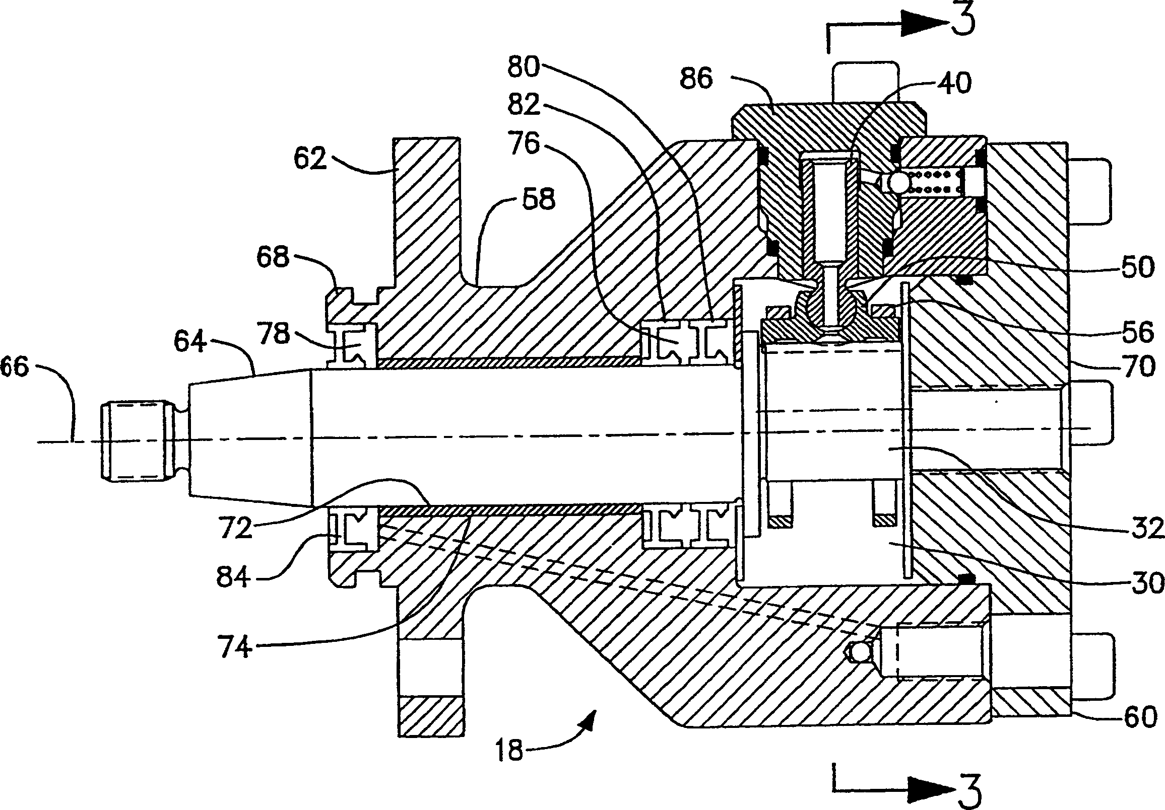
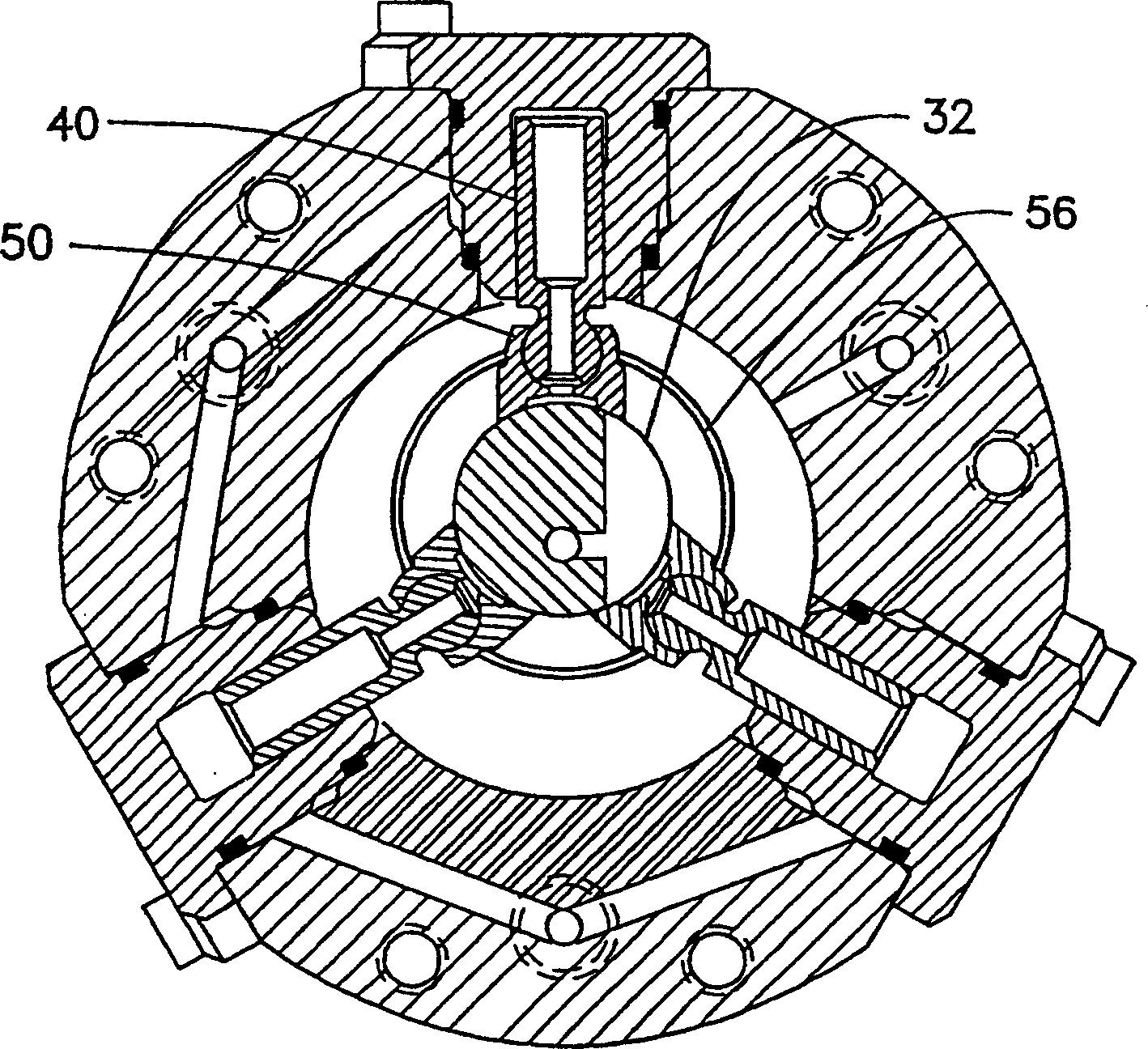
[0045] The internally driven fuel supply pump 18 consists of a pump housing 28 and an inner chamber 30 into which low-pressure fuel is fed through the fuel supply passage 20 . An eccentric drive member 32 is rotatable within cavity 30 about drive shaft 34 to increase fuel pressure in the manner described below. A plurality of plunger cylinders 36 or ...


PUM


Abstract

A fuel supply pump having a plurality of radially disposed plunger sleeves each containing a pumping plunger with a driven end reciprocally movable within the plunger sleeve between a pumping position and a filling position. The fuel supply pump includes a rotatable drive member and a plurality of sliding shoes. Each shoe has a first face adjacent a respective plunger driven end and a second face adjacent the drive member. In one variation, each shoe first face includes a socket which the plunger driven end snaps into and is captured by, creating a sliding shoe assembly. A case couples all of the sliding shoe assemblies. In another variation, the cage includes apertures which the plunger driven end snaps through, thereby capturing the plunger. The plunger driven end engages a seat included on the sliding shoe first face. Rotation of the drive member moves each shoe, and thereby, each plunger toward the pumping position. As one plunger is actuated toward the pumping position by the eccentric member at least one plunger is retracted to the filling position by the coupling of the cage. The coupling of the shoe assemblies and the cage allows for the creation of a controlled gap between the shoes second face and the drive member for part of the drive member rotation. Also a method of fuel supply pump assembly using sub-assemblies which can be assembled externally to the fuel supply pump body.

Description

technical field [0001] The invention relates to a fuel supply pump for injecting fuel into an internal combustion engine. More particularly, the present invention relates to a fuel supply pump having pumping plungers retained by sliding shoes or retainers. Background technique [0002] One type of commonly used oil supply pump has several plungers which reciprocate radially within corresponding pumping cylinders. As the plungers move toward the fill position, fuel is drawn into the pump cylinder. As the plungers move toward the pumping position, fuel under high pressure is expelled from the pump cylinder. These plungers can be internally or externally driven. In an internally driven fuel supply pump, a rotary drive member periodically drives the inner end of each plunger radially outward. In this type of pump, fuel is expelled from the cylinder during the radially outward stroke of the plunger and drawn into the cylinder during the radially inward stroke of the plunger. ...

Claims


Application Information

Patent Timeline
IPC IPC(8): F04B1/04F04B1/047F04B1/053F04B53/22
CPCF04B1/0408F04B1/0426F04B1/053F04B53/22F05C2225/12F05C2225/00F05C2203/08F05C2225/04F04B1/04
Inventor I·乔杰维克
Owner STANADYNE AUTOMOTIVE
Why Eureka
Try Eureka