Full automatic speed reducing clutch for washing machine

A deceleration clutch, fully automatic technology, applied in the field of washing machines, to achieve stable braking torque, reduce manufacturing costs, and eliminate effects

Inactive Publication Date: 2003-06-25
ANHUI JULONG TRANSMISSION TECH
View PDF0 Cites 11 Cited by
  • Summary
  • Abstract
  • Description
  • Claims
  • Application Information

AI Technical Summary

Problems solved by technology

[0003] The technical problem to be solved by the present invention is to design a fully automatic deceleration clutch for a washing machine to solve the technical problems of improving the washing efficiency of the washing machine, reducing the noise of the washing machine, and simplifying the structure of the deceleration clutch and its operating system

Method used


Image

  • Full automatic speed reducing clutch for washing machine
  • Full automatic speed reducing clutch for washing machine
  • Full automatic speed reducing clutch for washing machine

Examples


Embodiment Construction

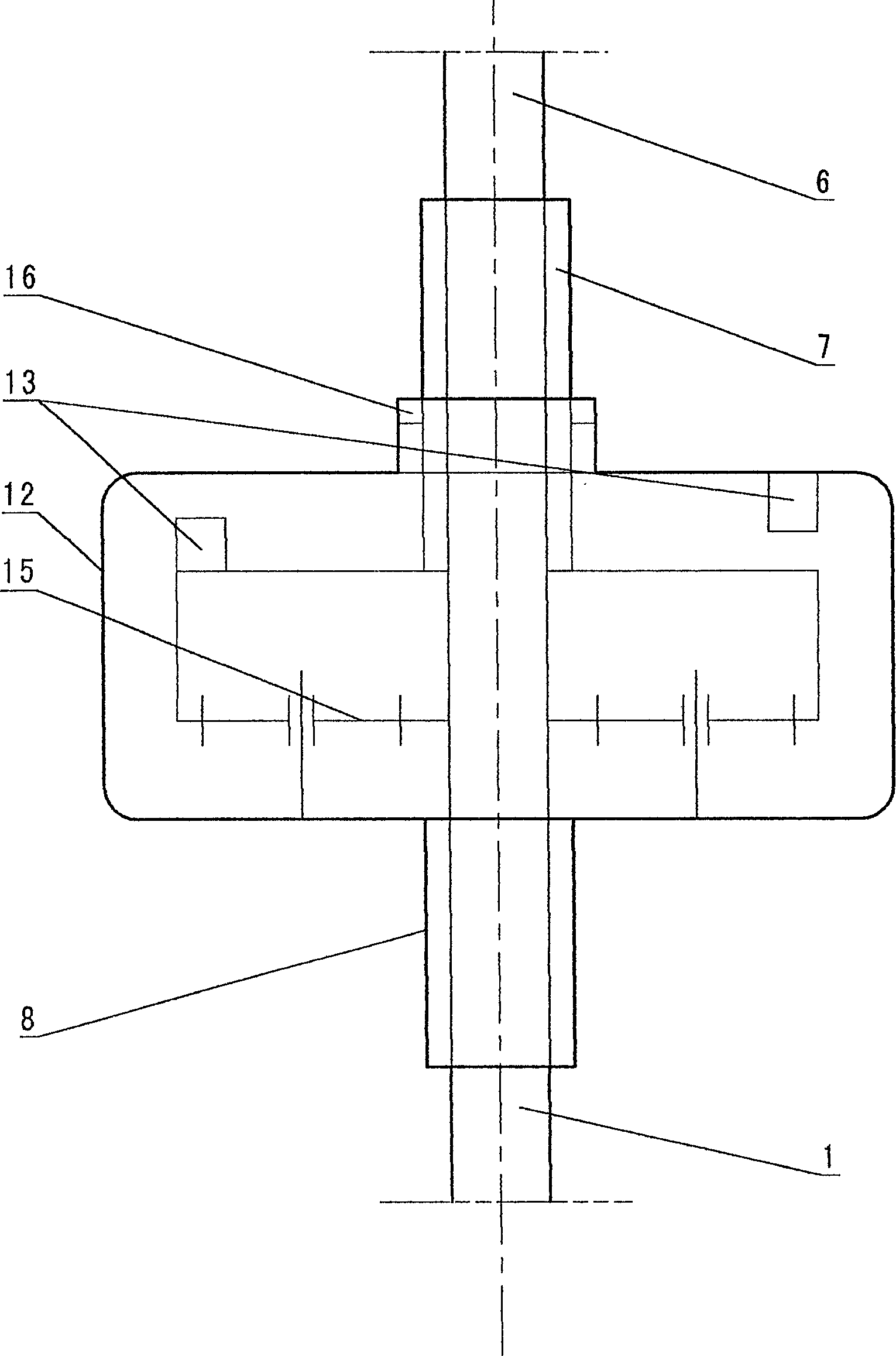
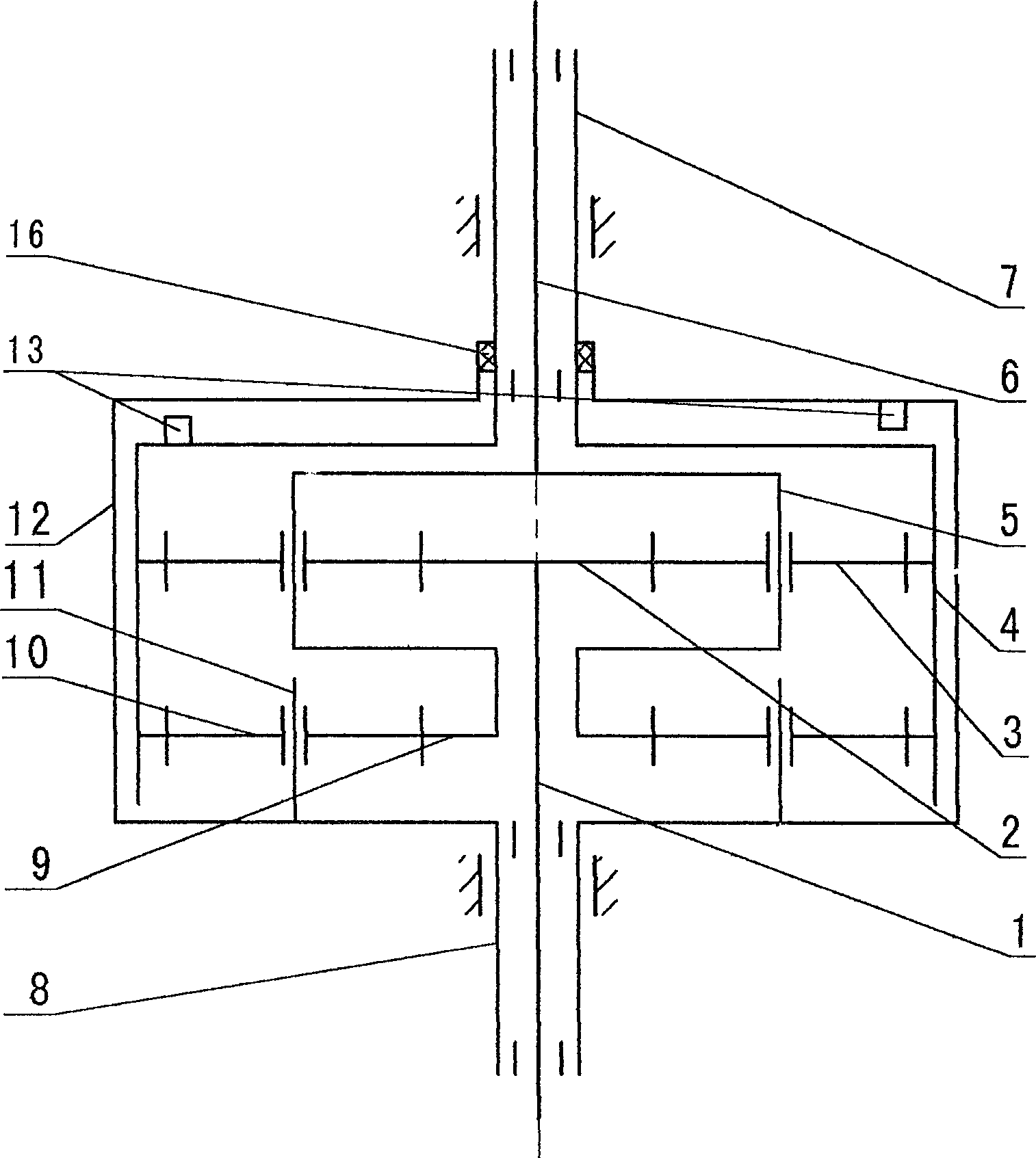
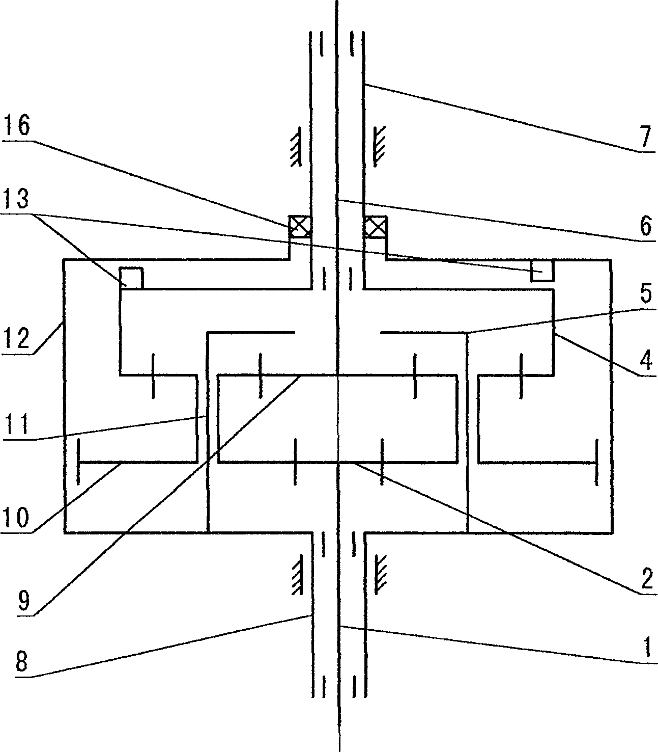
[0022] combine figure 1 The fully automatic deceleration clutch of the washing machine is composed of an input shaft 1, an output shaft 6, an output shaft sleeve 7, an input shaft sleeve 8, a brake wheel 12 and a double drive gear mechanism 15 installed inside the brake wheel 12, and the input shaft 1 is installed on In the input shaft sleeve 8, the output shaft 6 is installed in the output shaft sleeve 7, the input shaft sleeve 8 is fixedly connected to the lower end of the brake wheel 12, the input shaft 1, the output shaft sleeve 7 and the output shaft 6 are respectively connected with the double drive gear mechanism 15 Linked together, a clutch device 13 is housed between the brake wheel 12 and the output shaft sleeve 7 . A sealing ring 16 is installed between the upper opening of the brake wheel 12 and the output shaft sleeve 7 to prevent the outside world from polluting the double drive gear mechanism 15, and also to prevent the double drive gear mechanism 15 from damagi...


PUM


Abstract

The present invention relates to washing machine technology. The fully automatic speed reducing clutch consists of input shaft, input shaft sleeve, outupt shaft, output shaft sleeve, brake wheel and double-driven gear mechanism inside the brake wheel. The input shaft, the output shaft sleeve and the output shaft are connected separately to the double-driven gear mechanism; and between the brake wheel and the output shaft sleeve there is clutch unit. During washing, the output shaft and the outpuer shaft sleeve are rotated in opposite directions and in certain ratio to form repeated oscillation and rotation with strong kneading force. During dewatering, the clutch unit meshes the output shaft and the outupt shaft sleeve for high speed rotation in the same direction for centrifugal dewatering. The present invention makes washing machine simple, low in noise and long in service life.

Description

Technical field: [0001] The technical solution created by the invention relates to the technical field of washing machines, in particular to the deceleration clutch of washing machines. Background technique: [0002] Existing conventional deceleration clutch mainly is made up of input shaft, output shaft, output shaft sleeve, input shaft sleeve, braking wheel, the deceleration mechanism that is installed in braking wheel inside and the clutch part that is installed on the input shaft sleeve. In the washing condition, the output shaft is required to rotate repeatedly at low speed in both directions. The output sleeve and the brake wheel of the conventional deceleration clutch are integrated, and the deceleration mechanism generally only plays a simple deceleration function. When the brake wheel is braked, the output The axle sleeve is also braked, and the two-way rotation of the transmission motor can only drive the corresponding two-way rotation of the output shaft. In the ...

Claims


Application Information

Patent Timeline
Patent Type & Authority Applications(China)
IPC IPC(8): D06F37/40
Inventor 刘军薛华林
Owner ANHUI JULONG TRANSMISSION TECH
Why Eureka
Try Eureka