Combination floating body type multifunctional hydrant

A multi-functional, water supply plug technology, applied in the field of farmland irrigation, can solve the problems of poor water flow, lax automatic closing, uneven quality, etc., to eliminate the conditions of vacuum negative pressure formation, solve the operation vibration, and reduce the opening force Effect

Pending Publication Date: 2018-02-23
宋庆波
View PDF8 Cites 2 Cited by
  • Summary
  • Abstract
  • Description
  • Claims
  • Application Information

AI Technical Summary

Problems solved by technology

[0003] Since there is no unified national standard for the product of water supply hydrant, there is no professional scientific research institution for research projects, and there is no professional production enterprise, resulting in relatively lagging research and development of this product, single product function, and uneven quality. The following technical problems generally exist:
Due to the large quantity of water supply plugs, they are often loosened and leaked due to neglect of management. Before irrigation, it is necessary to organize personnel to check whether they are closed one by one in the field, which is labor-intensive and time-consuming, and management is difficult;
[0006] The third is that the opening and closing wrench is easy to imitate, resulting in the phenomenon of random opening and closing, private water theft and irrigation, and it is difficult to irrigate in an orderly manner according to the wheel irrigation system;
[0007] Fourth, the function is single, it can only be opened and closed manually, and it does not have comprehensive functions such as automatic closing, water metering, multi-directional water outlet, air intake and exhaust, and protection of pipelines;
[0008] Fifth, there is no water metering device, which cannot measure the amount of water to farmers, and cannot charge households according to the amount of water;
[0009] Sixth, most of the protective devices are built on site, which is labor-intensive and time-consuming, and occupies farmland
[0011] 1. The lifting track of the floating body valve is the slideway on the inner wall of the lower bolt body shell and the chute on the side wall of the floating body valve. In the process of lifting and landing, due to the impact of the water flow, the phenomenon of "stuck" in the slideway and the chute will occur in some cases, resulting in the lax automatic closing and water leakage
[0012] 2. The floating body water stop valve is an integral structure, and the buoyancy area for receiving water is relatively large. When the water pressure in the pipeline is high, the opening force of the water supply plug is very large, which causes the fast joint buckle, tenon and snap of the upper and lower plug bodies. Problems such as easy damage to drive nuts and other stress-bearing parts are more prominent;
[0013] 3. During operation, the water flows around the water stop valve of the floating body. Because the slideway and the chute have a certain influence on the water flow, the water flow is not smooth; at the same time, because the top surface of the floating body valve is large, it is easy to be on the top of the floating body when high-speed water flows through. negative pressure zone
[0015] 5. The water-stop rubber ring at the bottom of the upper bolt body is placed in the quick connector cap, which is easy to fall off and lose due to loose fixation;
[0016] 6. The connection between the water outlet of the upper bolt body and the hose is on-site binding connection, which is troublesome to use and has water leakage

Method used


Image

  • Combination floating body type multifunctional hydrant
  • Combination floating body type multifunctional hydrant
  • Combination floating body type multifunctional hydrant

Examples


Embodiment Construction

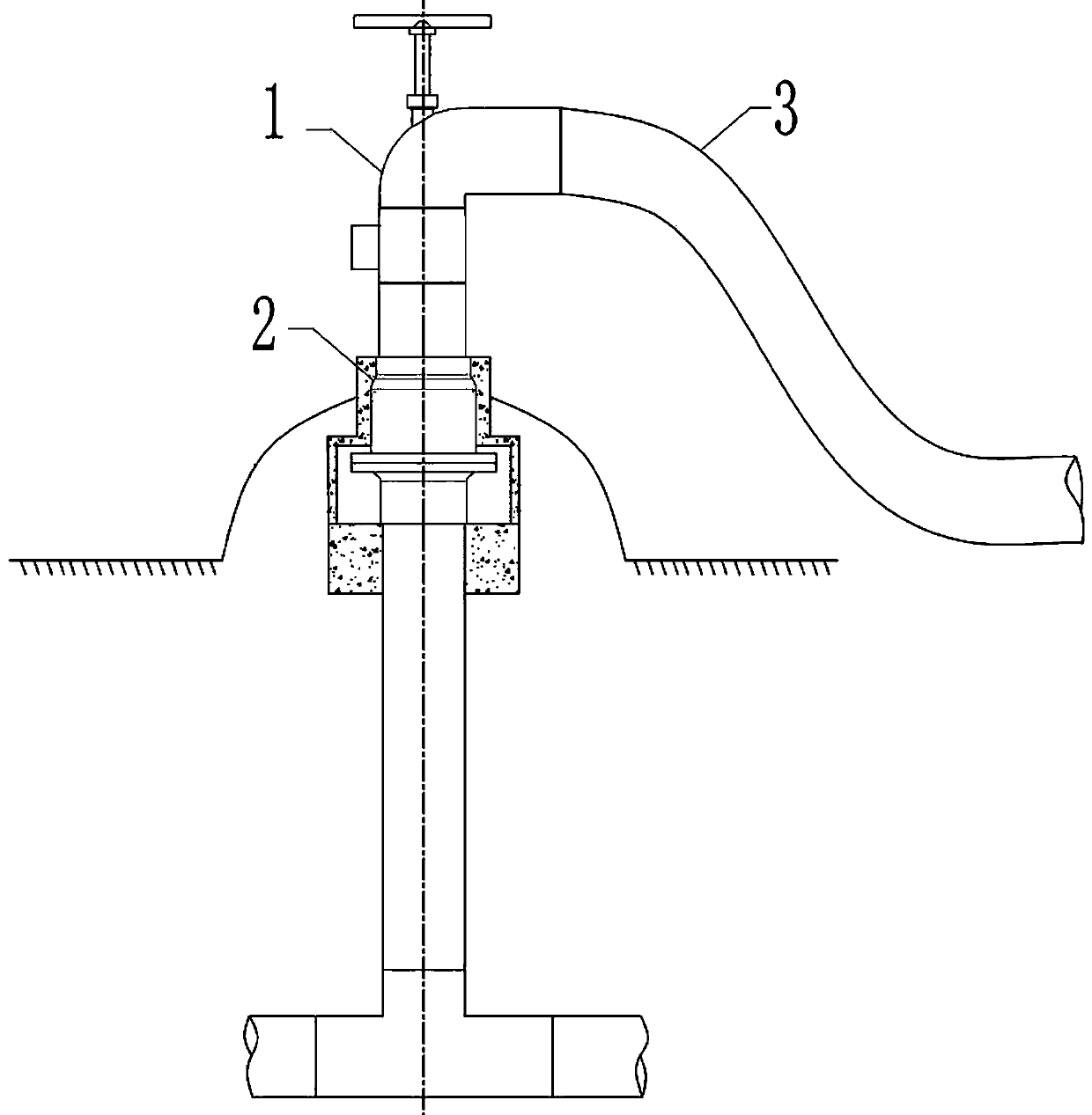
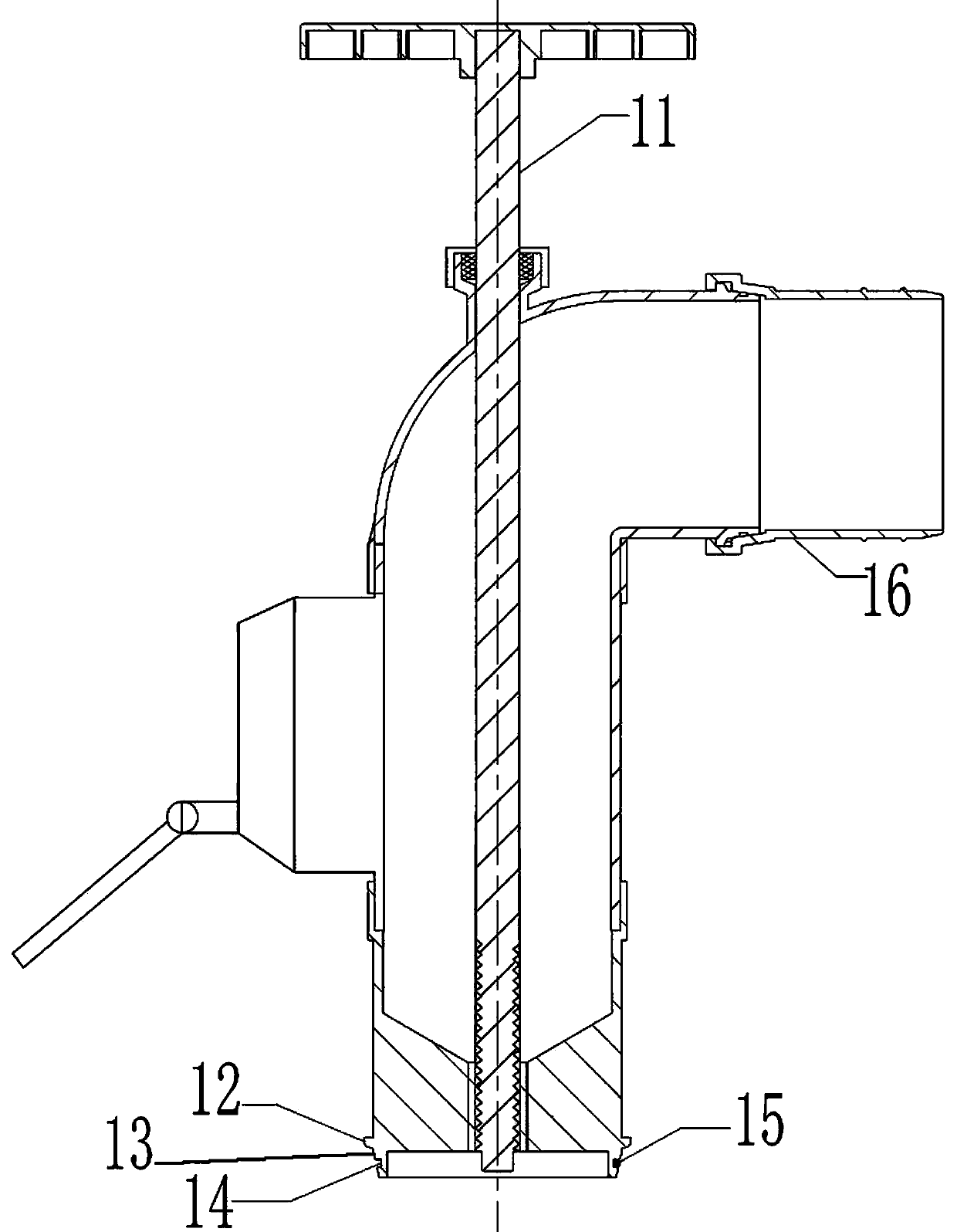
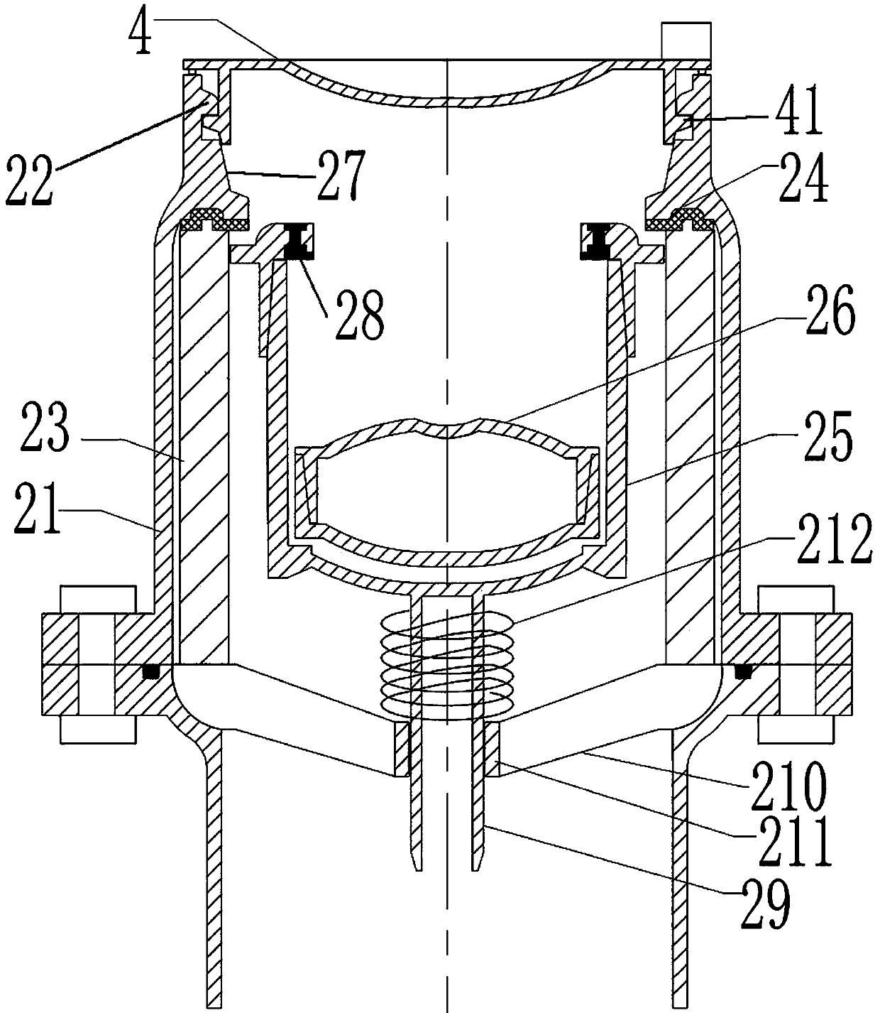
[0046] Attached below figure 1 to attach Figure 9 The present invention will be further described.

[0047] as attached figure 1 , attached figure 2 And attached image 3 As shown, a combined floating body multifunctional water supply cock includes an upper bolt body 1 and a lower bolt body 2, the lower end of the lower bolt body 2 is connected with the underground pipeline tee standpipe, and the upper bolt body 1 is vertically screwed with a screw Ⅰ 11. The lower bolt body 2 includes: a valve housing 21, which is airtight all around, and its lower end is provided with a water inlet, and its upper end is provided with a water outlet connected to the quick connector 12 of the upper bolt body 1; the large floating body 25 is cylindrical structure, which is installed in the valve housing 21 by sliding in the axial direction of the valve housing 21, N water holes 214 are arranged at intervals on the outer wall of the large floating body 25, and N is a natural number greater th...


PUM


Abstract

A combination floating body type multifunctional hydrant comprises an upper hydrant body and a lower hydrant body. The lower end of the lower hydrant body is connected with a three-way standpipe of anunderground pipeline, a screw rod I is vertically screwed on the upper hydrant, the lower hydrant comprises a valve housing, a large floating body, a small floating body, a water stop rubber ring IIand a water stop rubber ring III. By the adoption of water stop technology of the floating body valve, the self-closing function of the lower hydrant is achieved by utilizing the buoyancy of the waterin the pipeline, and the technical problems of manual-closing and frequent water leakage caused by the neglect of management of traditional hydrants are thoroughly solved; meanwhile, because when thecombination floating body type multifunctional hydrant is opening, firstly the small floating body is pushed down to discharge flow and reduce pressure, and then the large floating body is moved downand totally open, the twice-opening technology greatly decreases opening force. The flow can respectively pass through the outside and inside of the large floating body, the water flow is unhindered,the top surface of the small floating body is small, so that the condition for forming vacuum negative pressure is eliminated, the problem of hydrant run vibration caused by hindered water flow and vacuum negative pressure is thoroughly solved.

Description

technical field [0001] The invention relates to the field of farmland irrigation, in particular to a combined floating multifunctional water supply cock. Background technique [0002] In the farmland pipeline irrigation project, the water supply hydrant is responsible for the important function of water delivery and distribution from the underground pipeline to the field surface. It has a large area in the field and is closely related to the field agricultural machinery. It is the most important subsidiary of the pipeline project most used by the peasants. One of the facilities. [0003] Since there is no unified national standard for the product of water supply hydrant, there is no professional scientific research institution for research projects, and there is no professional production enterprise, resulting in relatively lagging research and development of this product, single product function, and uneven quality. The following technical problems generally exist: [000...

Claims


Application Information

Patent Timeline
Patent Type & Authority Applications(China)
IPC IPC(8): F16K1/44F16K1/54F16K31/20F16K31/30F16K35/10A01G25/16
CPCA01G25/16F16K1/44F16K1/54F16K31/20F16K31/30F16K35/10
Inventor 宋庆波
Owner 宋庆波
Why Eureka
Try Eureka