Dosing system for inking up rollers in printing machine

A metering system and printing machine technology, applied in the field of metering systems, can solve problems such as uneven ink transfer

Inactive Publication Date: 2003-06-25
MAN ROLAND MASCHINEN AG
View PDF6 Cites 1 Cited by
  • Summary
  • Abstract
  • Description
  • Claims
  • Application Information

AI Technical Summary

Problems solved by technology

Uneven ink transfer due to stress in the nip formed by the two rollers

Method used


Image

  • Dosing system for inking up rollers in printing machine
  • Dosing system for inking up rollers in printing machine
  • Dosing system for inking up rollers in printing machine

Examples


Embodiment Construction

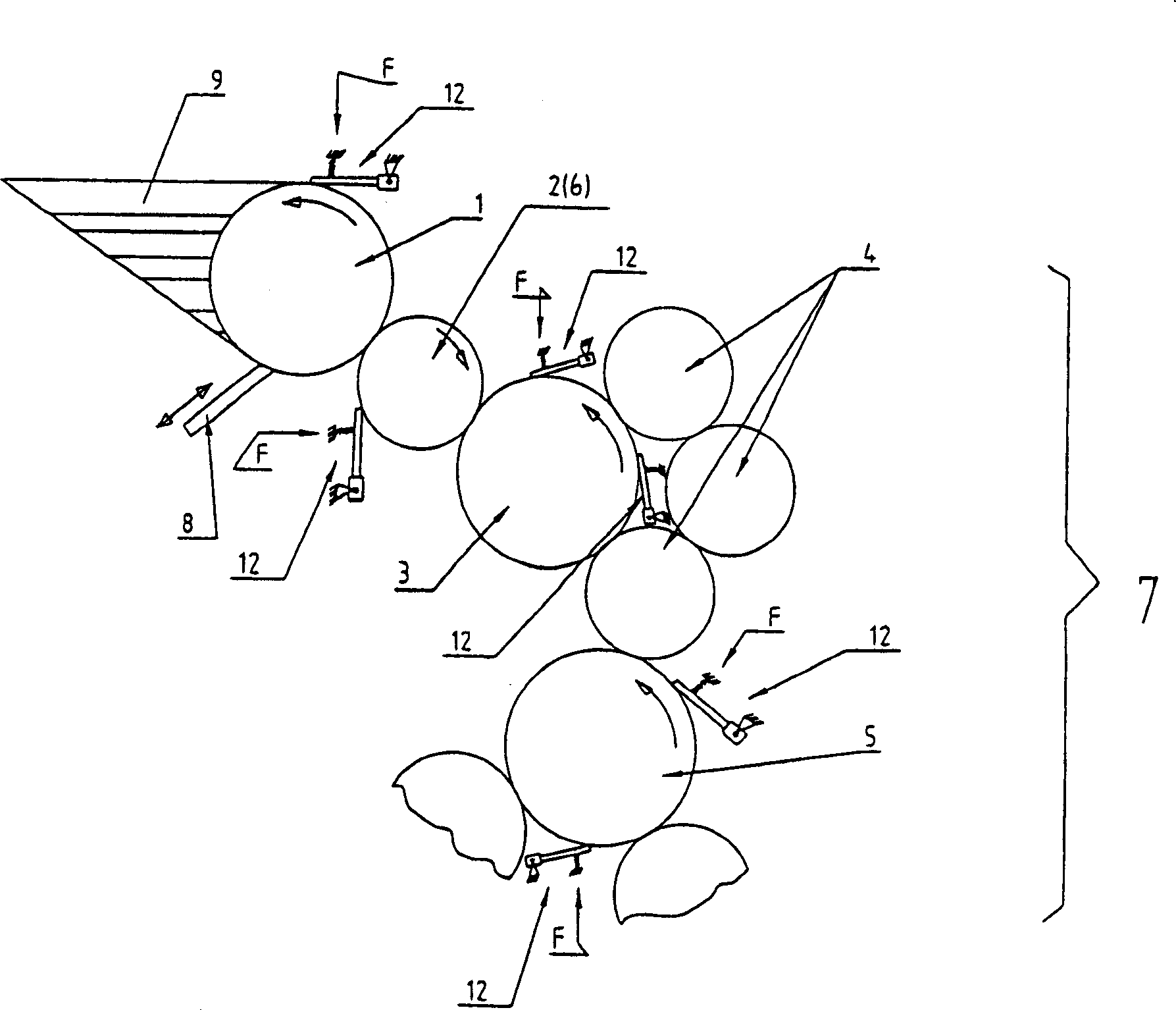
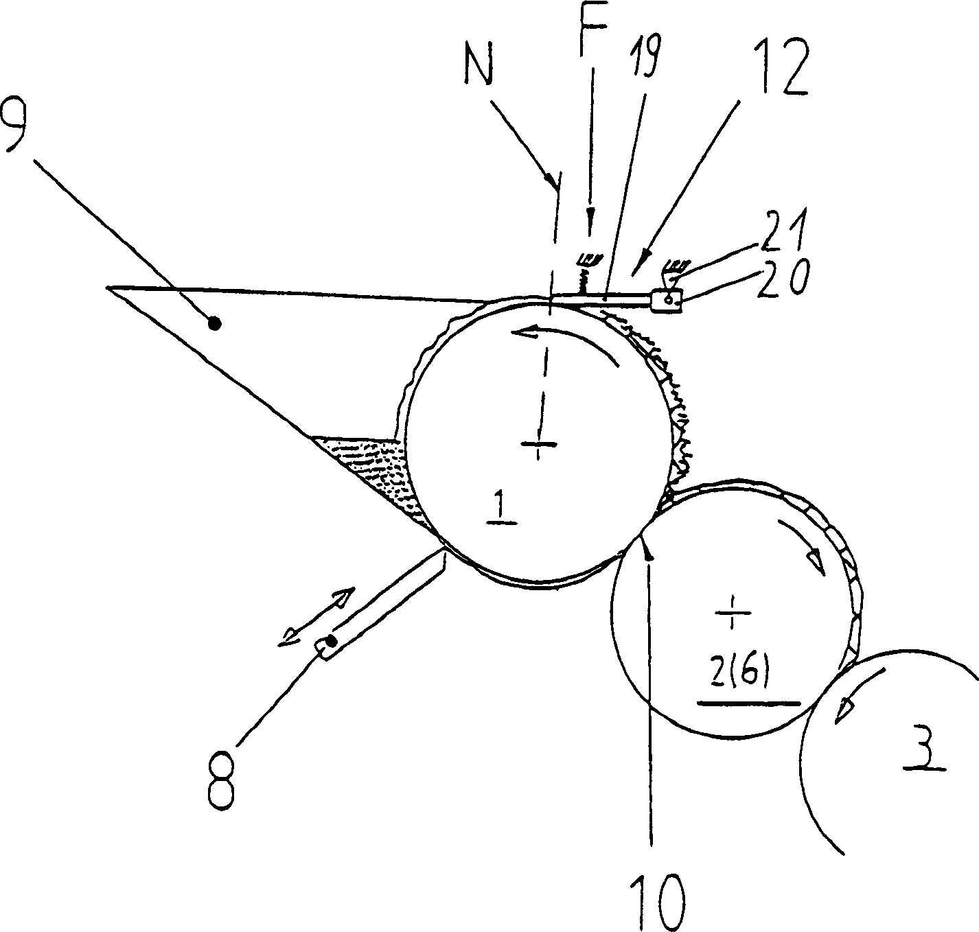
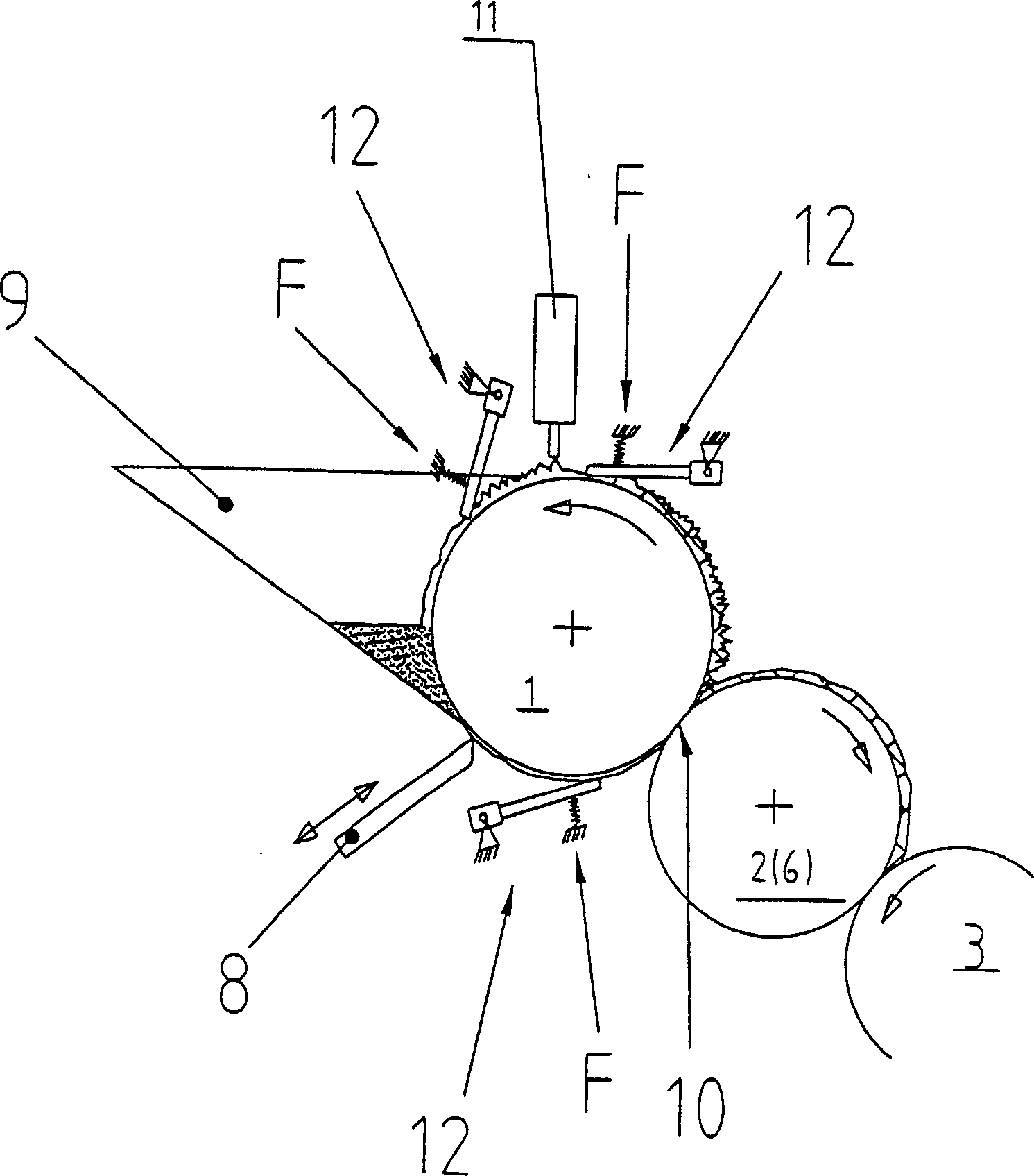
[0029] The offset printing unit of a sheet-fed rotary printing press essentially consists of an inking unit having an ink fountain roller 1 which is operatively connected to an ink fountain 9 which has an ink metering system 8 such as an ink slide valve. In addition, the inking unit has a siphon roller 2 or film roller 6 and an inking roller 3 of a downstream roller row 7 as a first series of inking rollers (rotatably driven and axially tracked). Roller train 7 leads to the plate cylinder and is known as a multiplicity of rollers, wherein for example the second series of inker rollers 5 (rotatably driven and axially tracked) is designed with inker rollers 4 in between.

[0030]At least one roller 1-6 of the inking unit is provided adjacently on its outer surface with a coating device 12 behind a contact zone 10 in which ink breaking or ink separation takes place, that it can be pressed against the roller 1-6 outer surface and preferably also separable therefrom. In this case,...


PUM


Abstract

The invention relates to a dosing system for inking up rollers in a printing machine. The aim of the invention is to create a dosing system which achieves, with a low level of complexity, a uniform and steady ink guidance on a roller surface and which noticeably improves the printing quality. To these ends, the invention provides that a coating device (12) is, in the rotational direction of a roller, engageably arranged on the outer surface of the roller (1), preferably after a contact zone (10) in which an ink separation occurs.

Description

technical field [0001] The invention relates to a metering system for inking rollers in a printing press according to the preamble of the independent claim, the metering system having at least one row of rollers leading to a plate cylinder, where the rollers can be supplied with ink from a storage container or varnish. The invention can preferably be used in an inking unit of a printing press, in particular in a film inking unit or a siphon inking unit, in which a fountain roller and a downstream transfer roller There is a rotatably arranged roller between them. Background technique [0002] DE3706602A1 discloses a printing press with a siphon inking unit. Here, the ink fountain roller is operatively connected to an ink fountain with an ink metering system, as described, for example, in DE 27 11 553 A1. In a printing press with a siphon inking device, the ink is periodically sucked up in strips by the ink fountain roller through the back and forth swing of the ink absorbi...

Claims


Application Information

Patent Timeline
Patent Type & Authority Applications(China)
IPC IPC(8): B41F31/00B41F31/04B41F31/10
CPCB41F31/00B41F31/04
Inventor H·契切茨舍P·胡梅尔R·奥尔特纳
Owner MAN ROLAND MASCHINEN AG
Why Eureka
Try Eureka