Ion injection device and method thereof

An ion implantation device and ion implantation technology are applied in the field of ion implantation device and ion implantation, and can solve the problems of waste, consumption, and shortening of the life of degassing device of harmful substances.

Inactive Publication Date: 2003-07-02
NISSIN ION EQUIP CO LTD
View PDF3 Cites 10 Cited by
  • Summary
  • Abstract
  • Description
  • Claims
  • Application Information

AI Technical Summary

Problems solved by technology

[0004] However, since the (a) operating state continuously produces an ion beam of the desired ion type, not only wasteful power or ion source feed gas is consumed, but also the ion source is depleted / degraded, accelerating the removal of harmful gases contained in exhaust gases and other devices. Substance outgassing equipment life shortened
Therefore, COO reduction cannot be achieved
[0005] On the other hand, although (b) running state can achieve COO reduction, almost all devices are stopped
Therefore, the disadvantage of this method is that the start-up of the ion implantation equipment is very slow when the ion implantation is resumed

Method used


Image

  • Ion injection device and method thereof
  • Ion injection device and method thereof
  • Ion injection device and method thereof

Examples


Embodiment Construction

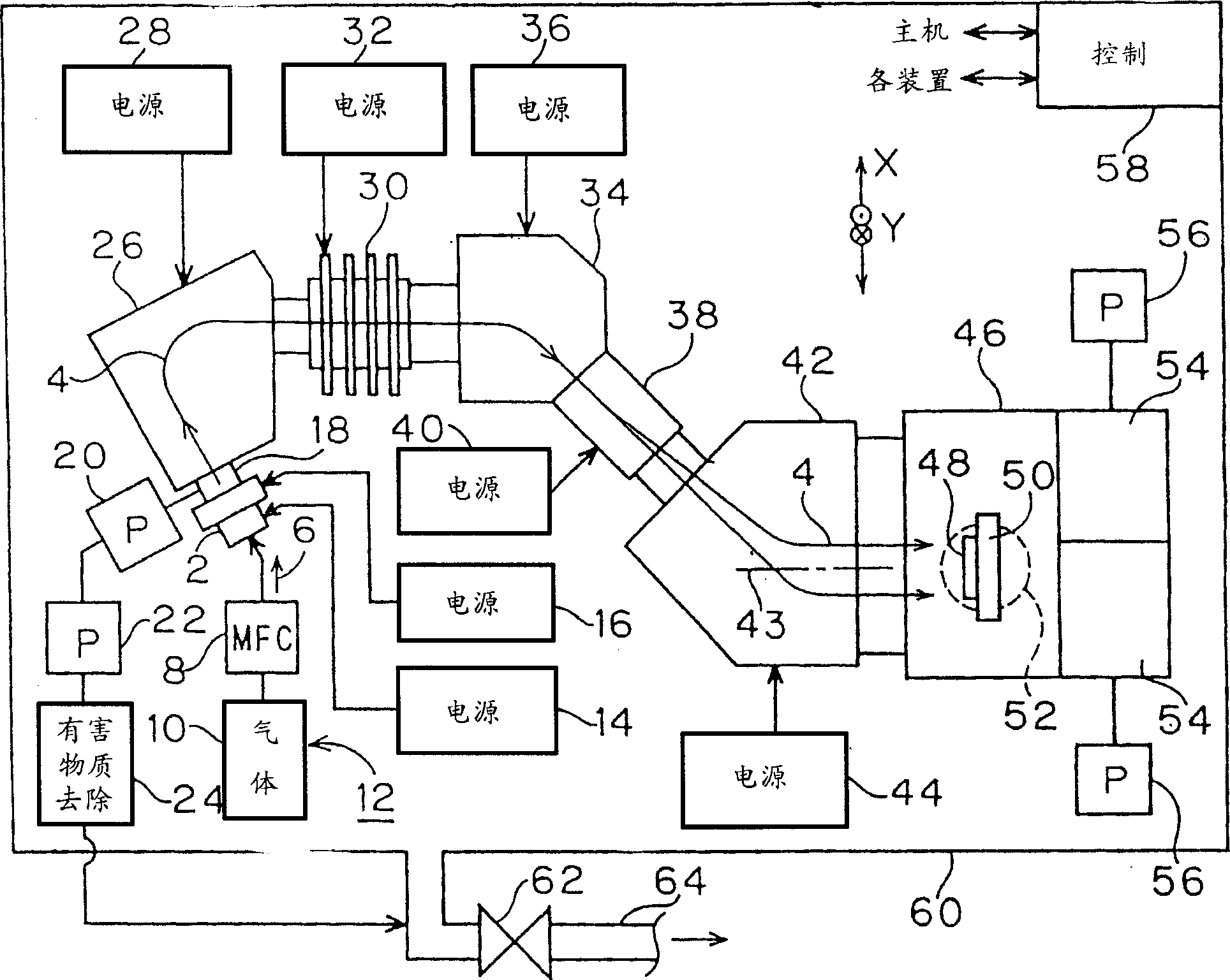
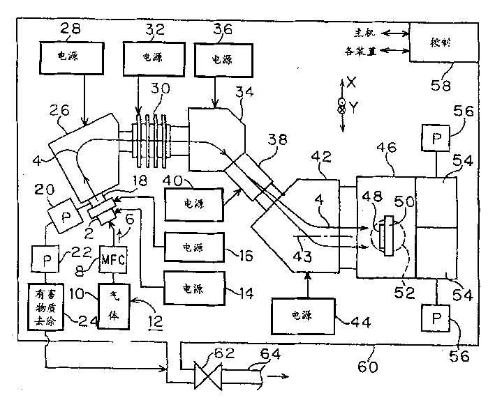
[0043] figure 1 It is a plan view of an embodiment of the ion implantation apparatus of the present invention. Such an ion implantation apparatus is disclosed in, for example, JP-A-8-115701 and JP-A-2001-143651, and the difference is that the control of the energy saving operation mode is performed by the control device 58 as described below.

[0044] figure 1 The ion implantation device shown is an example of a "hybrid scanning system". That is, the ion beam output from the ion source 2 is reciprocally scanned in the X direction (for example, the horizontal direction, in the following description of the specification) under the action of an electric field or a magnetic field. In addition, the substrate 48 as an injection target is mechanically scanned back and forth in the Y direction (the vertical direction, which is also the same in the following description of the specification) substantially orthogonal to the X direction. More specifically, figure 1 An embodiment of a hy...


PUM


Abstract

The ion implanting apparatus is provided with a control device which controls the operating state thereof in a period during which ion implantation is not carried out for a substrate in the state in any mode selected from the above (a) twilight mode in which the flow rate of the raw gas supplied to an ion source and the power supplied from a plasma producing power source are reduced to values capable of keeping plasma production in the ion source, (b) magnet-off mode in which in addition to the state in the twilight mode, the outputs from an energy separating magnet power source, scanning magnet power source and beam paralleling magnet power source are stopped, and (c) shut-down mode in which the supply of the raw gas is stopped and the outputs from the power sources are stopped.

Description

Technical field [0001] The present invention relates to an ion implantation apparatus and an ion implantation method that implant ions by irradiating a substrate (for example, a semiconductor substrate in the following description of the specification) with an ion beam. More specifically, the present invention relates to an ion implantation device and an ion implantation method, which can reduce the energy required to operate the ion implantation device. Background technique [0002] In the prior art ion implantation equipment, when ion implantation is not performed on the substrate, for example, in the period from when ion implantation has been completed on a certain group of substrates to when ion implantation on the next group of substrates is started, the equipment The operating status of is the following status (a) or (b). That is, the operating state (a) is: except that the substrate is not irradiated with an ion beam, the same state as the implantation process is maintaine...

Claims


Application Information

Patent Timeline
Patent Type & Authority Applications(China)
IPC IPC(8): C23C14/48H01J37/317H01L21/265
CPCH01J37/3171H01J2237/304H01L21/265
Inventor 松本贵雄织平浩一中尾和浩中村光则
Owner NISSIN ION EQUIP CO LTD
Why Eureka
Try Eureka