
Connector for linking panel and panel-linking method using said connector

A connector and connector terminal technology, which is applied in the parts, connections, and installation of connecting devices of connecting devices, etc., can solve the problems of increasing the number of electronic components and complicating electronic circuits.

Inactive Publication Date: 2003-07-09
JST MFG CO LTD
View PDF0 Cites 4 Cited by
  • Summary
  • Abstract
  • Description
  • Claims
  • Application Information

AI Technical Summary

Problems solved by technology

[0002] In recent years, with the diversification and improvement of functions of various electronic devices such as copiers, printers, and personal computers, the number of electronic components incorporated in these devices has increased, and electronic circuits have become more complicated

Method used


Image

  • Connector for linking panel and panel-linking method using said connector
  • Connector for linking panel and panel-linking method using said connector
  • Connector for linking panel and panel-linking method using said connector

Examples


Embodiment Construction

[0043] An embodiment of the present invention will be described below with reference to the accompanying drawings. Moreover, the present invention is not limited by this embodiment, and can be changed according to the method described at that time, and the structure and function of the changed part can be easily understood and guessed from the description of this embodiment, so its description is omitted. illustrate.

[0044] The electrical connector of the present invention will be described below using a plug-type connector, however, the present invention is not limited to the plug-type connector but can also be used for a receptacle-type connector.

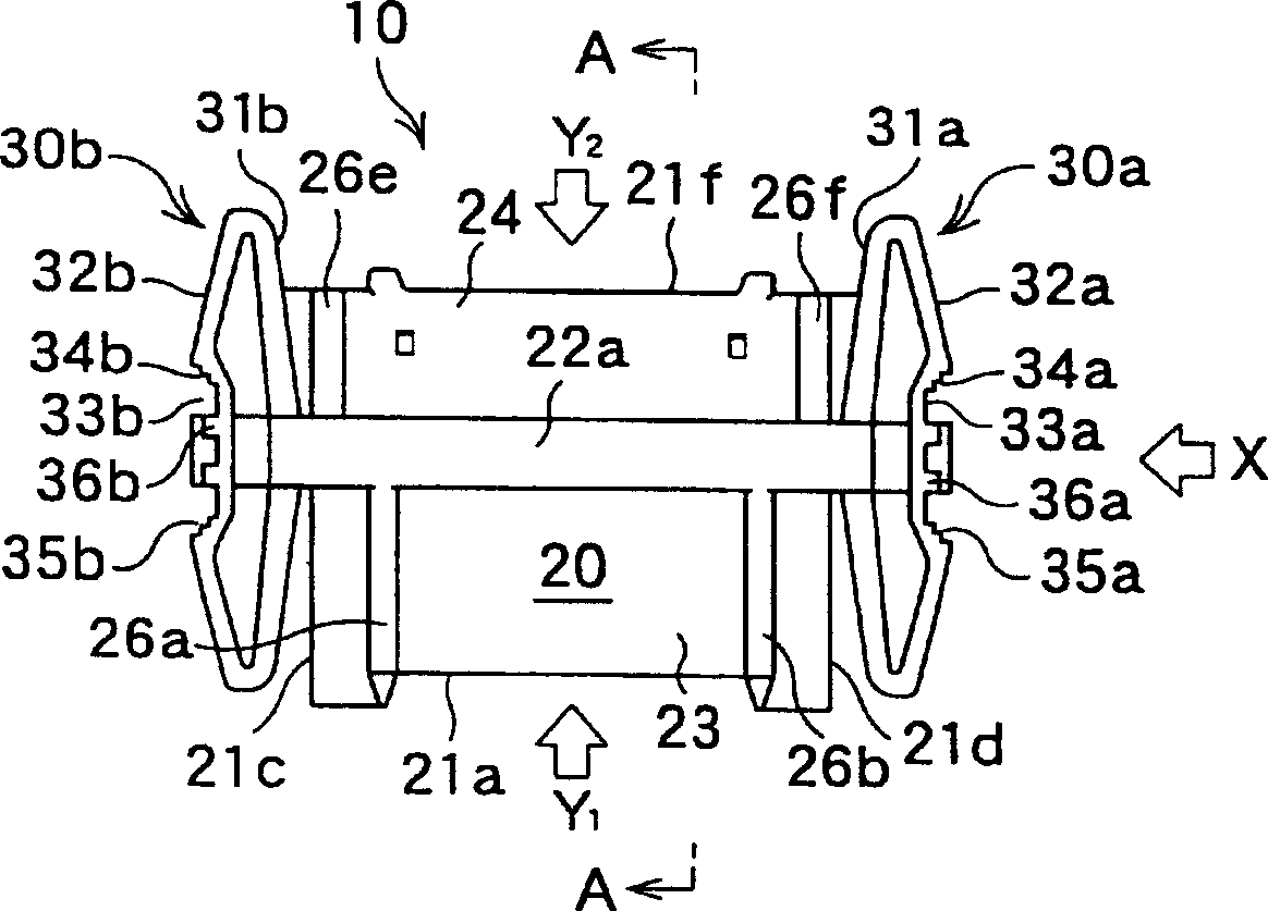
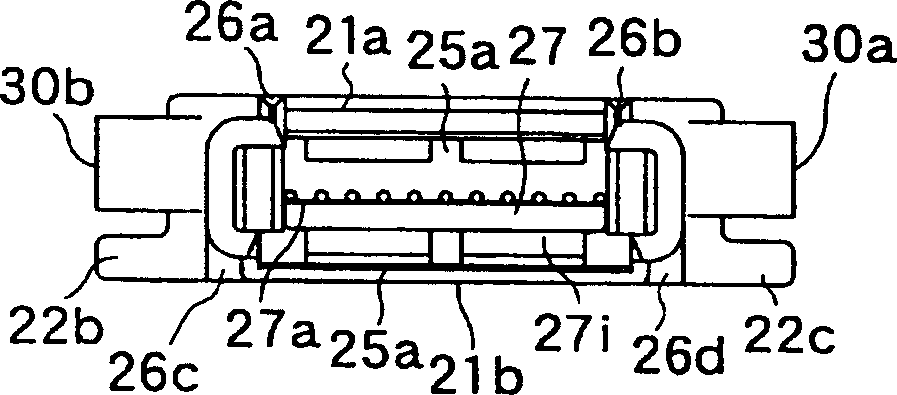
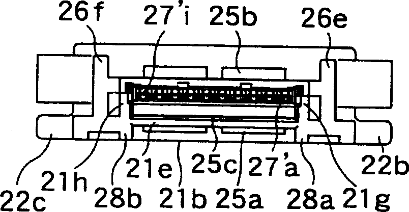
[0045] Figure 1(A) ~ Figure 1(D) Represent the plug type connector of an embodiment of the present invention, Fig. 1 (A) is the plan view of plug, Fig. 1 (B) is the front view seen from the arrow Y1 of Fig. 1 (A), Fig. 1 (C) is from The rear view seen by the arrow Y2 of Fig. 1(A), and Fig. 1(D) is the bottom view of the plug....


PUM


Abstract

A connector for coupling panels which does not influence upon an electrically connected part of a connector to be attached to a panel even if an external force is applied to the panel. The connector for coupling panels comprises an insulating housing(20) having a through hole(25) therein through which connector terminals are fitted therein, flanges (22a) orthogonal to a direction of insertion and removal through the insulating housing and projected outwardly from at least one wall face of the insulating housing, comprising front and back faces, respectively, and a pair of retainer members (30a, 30b) having flexibility, fixedly attached to both side ends or both up-down ends of the insulating housing, respectively, wherein the retainer members are provided with a pair of retainer stepped parts(34a, 35a / 34b, 35b), facing each other, and there is a gap for allowing fixture of the panel between the front and back faces of the respective flanges and the respective retainer stepped parts of the retainer members.

Description

technical field [0001] The present invention relates to a connector for connecting panels such as printed circuit boards on which electronic components are mounted, and in particular, to a connector for connecting to each other electrically and mechanically or only mechanically, and for connecting two panels using the connector at a predetermined interval Panel connection method. Background technique [0002] In recent years, with the diversification and improvement of functions of various electronic devices such as copiers, printers, and personal computers, the number of electronic components incorporated in these devices has increased, and electronic circuits have become more complicated. These electronic components are usually mounted on a panel, and are electrically connected to each other on the panel. However, as the number of electronic components increases and circuits become more complicated, these electronic components are not mounted on one panel, but are dispers...

Claims


Application Information

Patent Timeline
Patent Type & Authority Applications(China)
IPC IPC(8): H01R12/70H01R13/74
CPCH01R12/7082H01R13/743H01R12/7023H01R12/71H01R12/73
Inventor 后丰正木克之滨田雄介
Owner JST MFG CO LTD
Learn More