Wing in ground effect vehicle with endplates

An end plate and air cushion technology, applied in the field of WIG with end plates, can solve the problems of unrealistic thickness, wrong structure of end plate 57, lack of stability, etc.

Inactive Publication Date: 2003-07-09
КОСМОС ХОЛДИНГЗ ЛИМИТЕД
View PDF0 Cites 12 Cited by
  • Summary
  • Abstract
  • Description
  • Claims
  • Application Information

AI Technical Summary

Problems solved by technology

The thickness that the end plate 57 is not designed to be and is continuously submerged in the trough is completely impractical as the resistance is sufficient to pull down the WIG
Furthermore, Moore concludes that in Sea State 4, at an immersion depth of 4.3' (1300mm) and a speed of 265 knots (136m / s), the high lateral forces on yaw would produce structural errors in the endplate 57
[0015] The prior art end plates discussed above generally have very high resistance characteristics and lack stability if submerged in water

Method used


Image

  • Wing in ground effect vehicle with endplates
  • Wing in ground effect vehicle with endplates
  • Wing in ground effect vehicle with endplates

Examples


Embodiment Construction

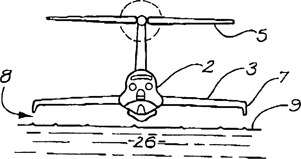
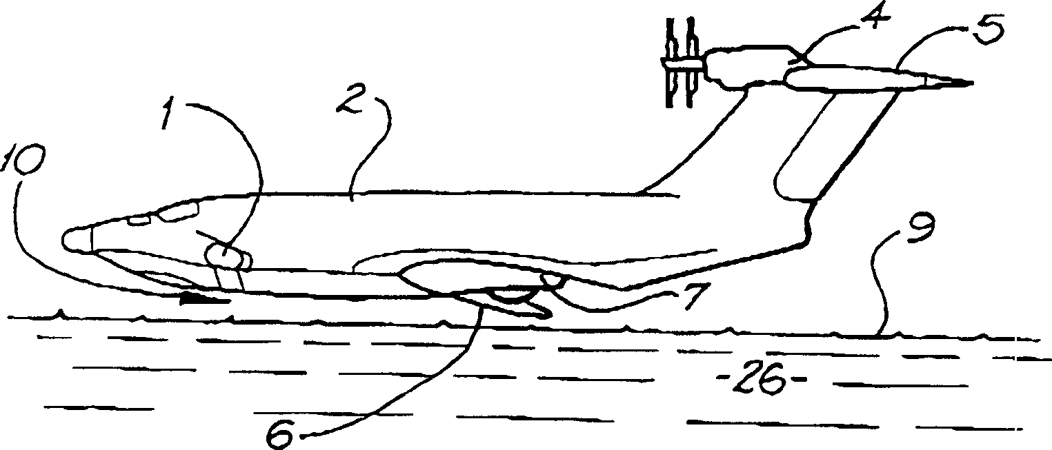
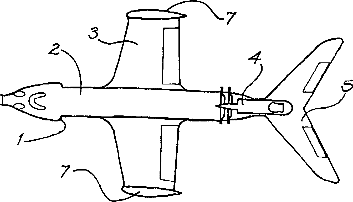
[0129] Figures 6(a) to 6(c) A winged hovercraft according to a preferred embodiment of the present invention will be described. The winged hovercraft has a fuselage 2 and a wing structure 3 with opposing wing tops. A pair of end plates 17, each end plate having a proximal base 33, a bottom or distal end 19, a leading edge 20 and a trailing edge 22, extend downward from the end plate wall 34 at the wing tip to the fuselage 2 and the machine. Below the wing structure 3. As shown in Figure 6(b), this allows the end plate 17 to be submerged in water 26 during flight while keeping the fuselage 2 and wing structure 3 in flight. In flight, the end plates are typically slightly submerged below the surface 9 of the water 26, even in the troughs 18 of the waves 21, as shown in the sectional view of Fig. 6(b). Since there is no air gap between the distal end 19 of the end plate 17 and the water 26, the WIG's induced drag is reduced, thereby increasing the WIG's lift / drag ratio. In o...


PUM


Abstract

A Wing In Ground Effect Vehicle has a pair of supercavitating endplates ( 17 ) which extend below the fuselage ( 2 ) such that they can be immersed in water during flight thereover. The endplates have a nose ( 28 ) defining a leading edge ( 20 ) and adapted to generate a supercavity. The endplates ( 17 ) typically pivot about a pivot axis P to provide a stabilising weathercock-type effect.

Description

technical field [0001] This invention relates to winged hovercraft (WIGs), and more particularly to WIGs having endplates for flight over water. Background technique [0002] A significant portion of the drag of a transport aircraft consists of induced drag. Flying ground effect close to the ground or water reduces this drag. A number of WIGs have been developed and flown. [0003] Several large WIG designs have been proposed, but have not yet been built. These plans are outlined in two reports, "Development of Hovercraft (First Revised Edition)" by Peter J. Mantle (DTNSRDC Report 80 / 012 (Rev. 4727) 1980.1) (hereinafter referred to as the Mantle Report), and " Hydrofoil Research" (Prospective Research Project Agency, 9 / 30 / 94) (hereinafter referred to as the ARPA report). [0004] WIGs are usually flown over water because the altitude of the ground varies greatly. All existing WIGs fly entirely over water at the height of the highest wave expected to be encountered plus ...

Claims


Application Information

Patent Timeline
Patent Type & Authority Applications(China)
IPC IPC(8): B60V3/08B60V1/08B60V1/22
CPCY02T50/162B60V1/22B60V1/08B60V1/18
Inventor 肯·R·艾伦
Owner КОСМОС ХОЛДИНГЗ ЛИМИТЕД
Why Eureka
Try Eureka