
Hydraulic brake device for differential mechanism

A technology of hydraulic brakes and differentials, which is applied in the field of brakes and differential hydraulic brakes, can solve the problems of inability to turn on the spot, different driving torques, and large energy consumption loss, etc., and achieves a simple and reasonable structure, The effect of stability improvement and structural stability

Active Publication Date: 2016-08-17
ZHEJIANG LIULIN AGRI MACHINERY
View PDF5 Cites 5 Cited by
  • Summary
  • Abstract
  • Description
  • Claims
  • Application Information

AI Technical Summary

Problems solved by technology

At present, there are devices on the market that use a differential device for braking or steering. Although it can output different speeds for the left and right wheels and complete the turning of the car, there is a large energy loss and slipping due to different driving torques, which cannot be achieved. Issues such as turning in place

Method used


Image

  • Hydraulic brake device for differential mechanism
  • Hydraulic brake device for differential mechanism
  • Hydraulic brake device for differential mechanism

Examples


Embodiment Construction

[0038] Below in conjunction with accompanying drawing, the present invention will be further described with specific embodiment,

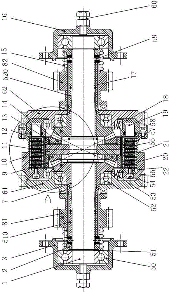
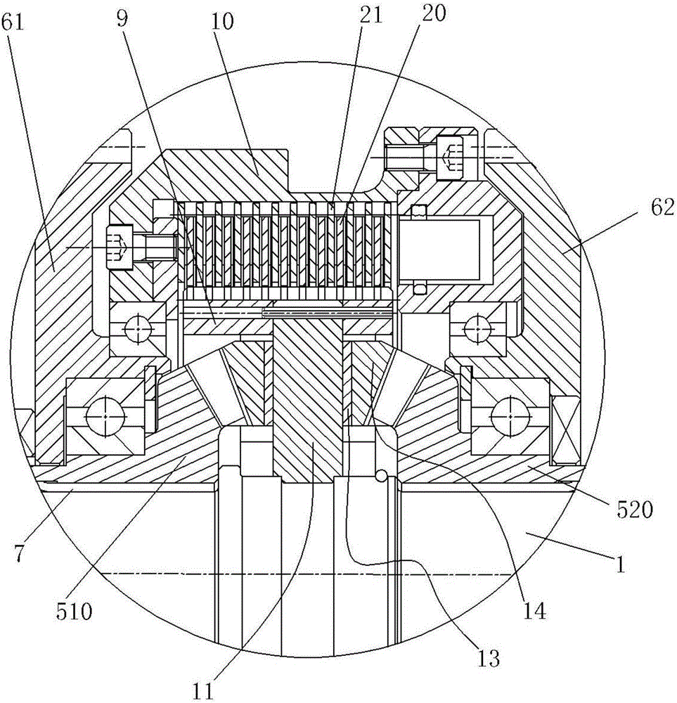
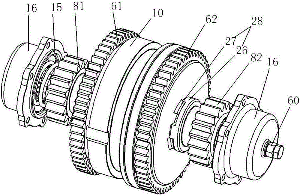
[0039] see Figure 1-8 : a differential hydraulic brake device, comprising a planetary gear differential and a hydraulic brake mechanism, the planetary gear differential and the hydraulic brake mechanism are meshed with each other; the hydraulic brake mechanism includes several separating plates 21, and the separating plate 21 and An inner disk 20 is arranged between the separation plates 21, and the inner disk 20 is movably arranged on the planetary gear differential, wherein the leftmost separation plate 21 is fixedly connected to the gear differential, and the rightmost separation plate 21 is on the right side. A hydraulic cylinder is provided to push the separating plate 21 and the inner disc 20 to be in close contact; the planetary gear differential is externally connected with a power device.

[0040] Including a case body 10 and a different...


PUM


Abstract

The invention belongs to the field of differential mechanisms and in particular relates to a hydraulic brake device for a differential mechanism. The hydraulic brake device for the differential mechanism comprises a planetary gear differential and a hydraulic brake mechanism which are mutually meshed; the hydraulic brake mechanism comprises a plurality of separating plates, an inner disc is arranged between the separating plates, the inner disc is movably arranged on the planetary gear differential, the leftmost separating plate is fixedly connected with a gear differential, and a hydraulic cylinder which is used for pushing the separating plates and clings to the inner disc is arranged at the right side of the rightmost separating plate; a power device is connected outside the planetary gear differential, and rotating speed of an output end of the planetary gear differential and steering are controlled by virtue of the hydraulic brake mechanism. The hydraulic brake device for the differential mechanism has the advantages that structure is simple, in-situ steering can be realized, output rotating speeds of the left side and the right side can be conveniently adjusted, and power output is stable.

Description

technical field [0001] The invention belongs to the technical field of brakes, and relates to a brake device that adopts differential transmission and cooperation, in particular to a differential hydraulic brake device. Background technique [0002] A vehicle differential is a mechanism that enables the left and right (or front and rear) drive wheels to rotate at different speeds. It is mainly composed of left and right side shaft gears, two planetary gears and a gear carrier. The function is to make the left and right wheels roll at different speeds when the car is turning or driving on an uneven road, that is, to ensure that the driving wheels on both sides perform pure rolling motion. The differential is installed to adjust the speed difference between the left and right wheels. [0003] The principle of the differential is mostly: the power of the engine enters the differential through the transmission shaft, directly drives the planetary wheel carrier, and then the pla...

Claims


Application Information

Patent Timeline
Patent Type & Authority Applications(China)
IPC IPC(8): F16H48/08F16H48/22F16H48/32F16H48/38
CPCF16H48/08F16H48/22F16H48/32F16H48/38F16H2048/201
Inventor 郑春玲缪建平郑宇
Owner ZHEJIANG LIULIN AGRI MACHINERY
Learn More