Circuit for restraining surge current

A technology for suppressing circuits and inrush currents, applied in circuit devices, emergency protection circuit devices for limiting overcurrent/overvoltage, emergency protection circuit devices, etc. Easy to damage and other problems, to suppress surge, avoid high energy consumption, and avoid vulnerable components

Inactive Publication Date: 2003-07-23
DELTA ELECTRONICS INC
View PDF0 Cites 17 Cited by
  • Summary
  • Abstract
  • Description
  • Claims
  • Application Information

AI Technical Summary

Problems solved by technology

When the power supply of the power supply is initially turned on, the resistor R performs a preliminary current limiting function. Since the capacitor C has not started charging at this time, the overall current value is quite high, which may damage the electronic components on the power supply; then, the capacitor C The charging of C is completed and the current decreases, but its value is still very high, so that the electric group R continues to emit a lot of heat; finally, the controlled switch SW such as a relay (Relay) is turned on to achieve the current bypass ) The effect of the resistor R prevents the overall efficiency from being reduced due to the heat dissipation of R. However, the disadvantage of this method is that the characteristic of the relay is that it is easily damaged when it is continuously on, and another form of surge is generated at the moment the relay is turned on. The overall power supply is easily damaged

Method used


Image

  • Circuit for restraining surge current
  • Circuit for restraining surge current
  • Circuit for restraining surge current

Examples


Embodiment Construction

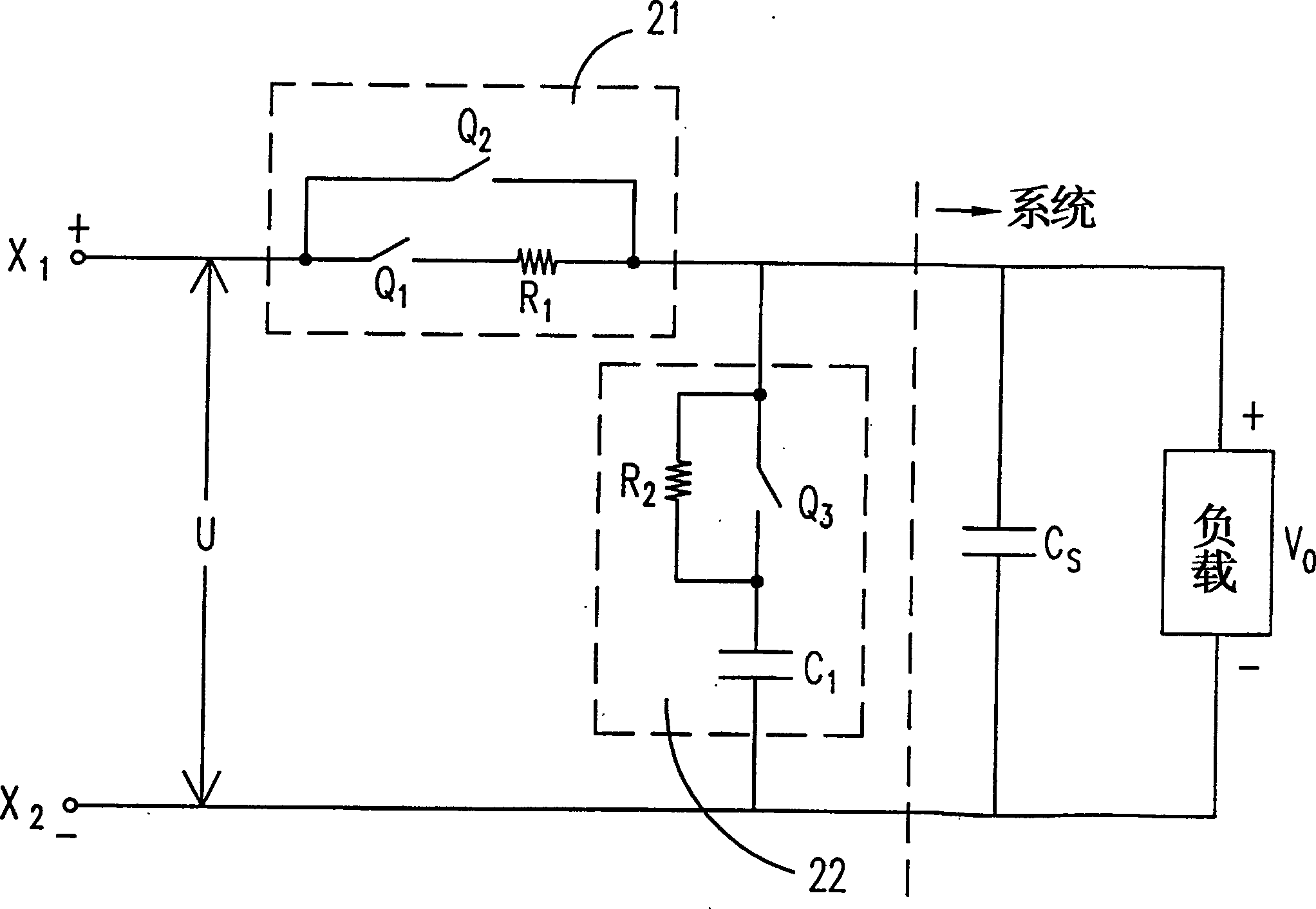
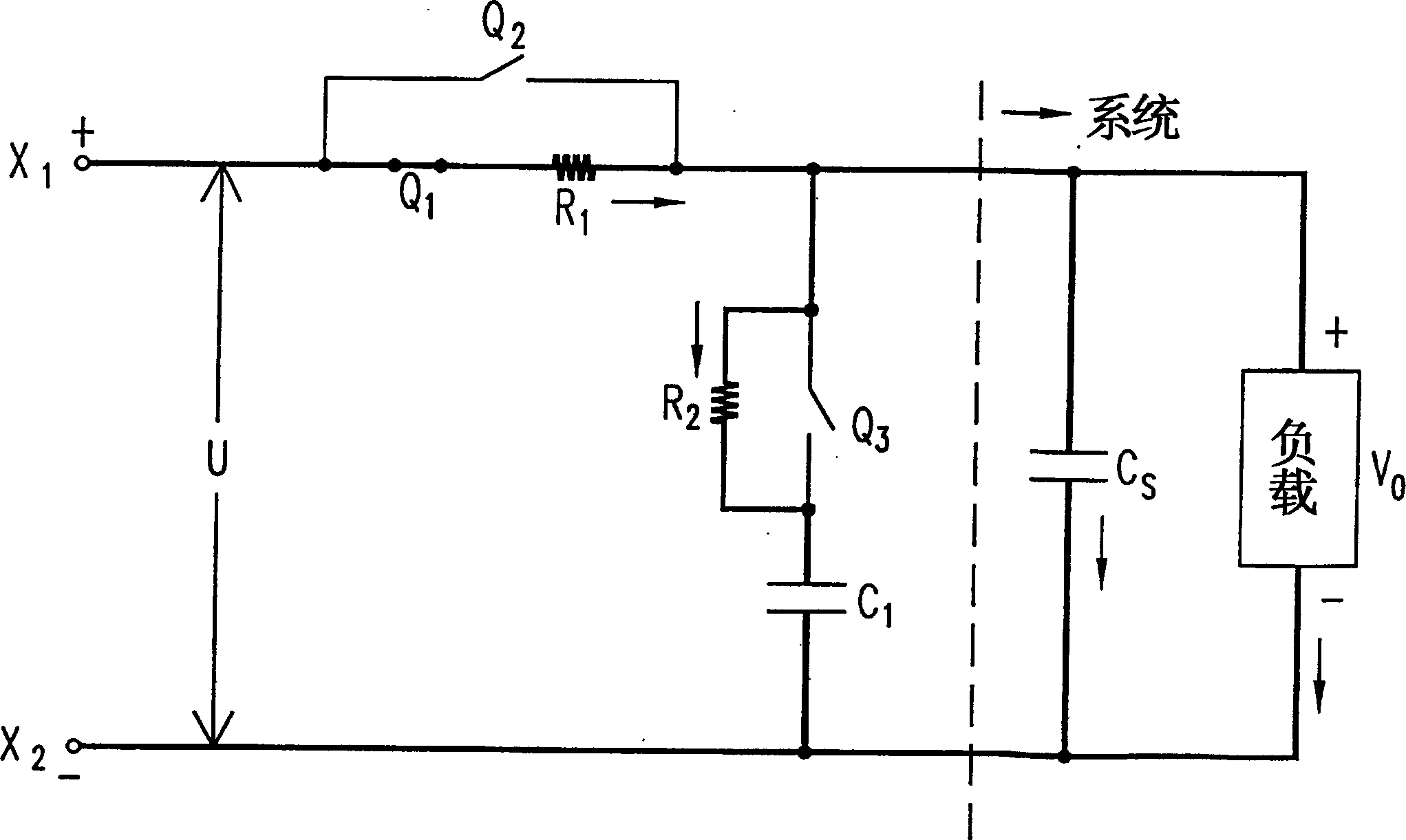
[0031] please see figure 2 , which is a circuit diagram of a surge current suppression circuit in a preferred embodiment of the present invention. The surge current suppression circuit is located between a DC input voltage U and a load system energy storage capacitor Cs, which is achieved by means of two resistors R1, R2, three controlled switches Q1, Q2, Q3 and an energy storage capacitor C1 Achieve the function of suppressing the surge.

[0032] The surge current suppression circuit of the present invention includes a first current limiting circuit 21 and a second current limiting circuit 22 . The first current limiting circuit 21 is composed of a first resistor R1, a first controlled switch Q1 and a second controlled switch Q2, wherein one resistor R1 is connected in series with the first controlled switch Q1, and the second controlled switch Q2 is connected to the first resistor R1 and the first controlled switch Q1 are connected in parallel. The second current limitin...


PUM


Abstract

The circuit for restraining the surge current is located between the DC voltage and a load. The load has the parallel energy storage capacitnace. The suppressing circuit includes the first current-limited circuit and the second current-limited circuit. The first current-limited circuit includes the first resistance, the first controlled switch and the second controlled switch. The first resistance is connected to the first controlled switch in series. The connection between the second current-limited circuit and the first resistance as well as the first controlled switch is the parallel connection. The second current-limited circuit includes the second resistance and the third controlled switch-capacitor. The second resistance is connected to the third controlled switch in parallel as well as connected to the energy storage capacitor in series.

Description

technical field [0001] The invention relates to a surge current suppressing circuit, in particular to a surge current suppressing circuit applied to a power input module in a communication power supply system. Background technique [0002] Inrush current (Inrush Current) usually occurs at the moment when the power supply is initially turned on. At this time, unexpected or unwanted transient current (Transient Current) will be generated, which can easily generate noise and even cause damage to power supply components or loads. [0003] figure 1 It shows an inrush current suppression circuit (InrushLimiting Current) applied to a DC power supply in the prior art. A resistor R and a receiving capacitor are connected between the input DC voltage U and the system (including a load and a parallel system energy storage capacitor Cs). Control the switch SW and a capacitor C to complete the function of suppressing the surge. When the power supply of the power supply is initially tur...

Claims


Application Information

Patent Timeline
Patent Type & Authority Applications(China)
IPC IPC(8): H02H9/02
Inventor 潘光华许智明
Owner DELTA ELECTRONICS INC
Why Eureka
Try Eureka