
Eureka
For R&D, Eureka makes reading and utilizing patents & technical documents easy.
Eureka AIR
Designed for self-driven R&D workflows. Generate viable solutions, solve complex R&D challenges, empower your innovation with AI.

Eureka Materials
Designed for material experts only. Revolutionize your material R&D, from search, analyze, to developing new materials.

TechResearch
Generate reliable direction feasibility study reports for your R&D in just a few steps.

TechSeek
Discover and master advanced knowledge NOW. Basics, ideas, possibilities, all at once.

TechMind
As an expert in R&D Theories, TechMind can generates customized viable solutions instantly.

TechRisk
Analyze your overall solution with one click, know your potential R&D risks in advance.

TechMonitor
Get weekly tech updates, stay abreast of the latest tech innovations and key insights.
Ice maker working state display method
A technology of working status and display method, which is applied in the direction of ice making, ice making, lighting and heating equipment, etc., and can solve the problem that it is difficult to judge whether the ice machine is working normally. Impact and other issues
- Summary
- Abstract
- Description
- Claims
- Application Information
AI Technical Summary
Problems solved by technology
Method used
Image

Examples
Embodiment Construction
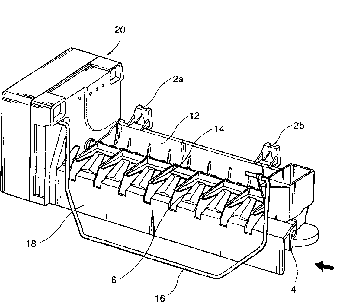
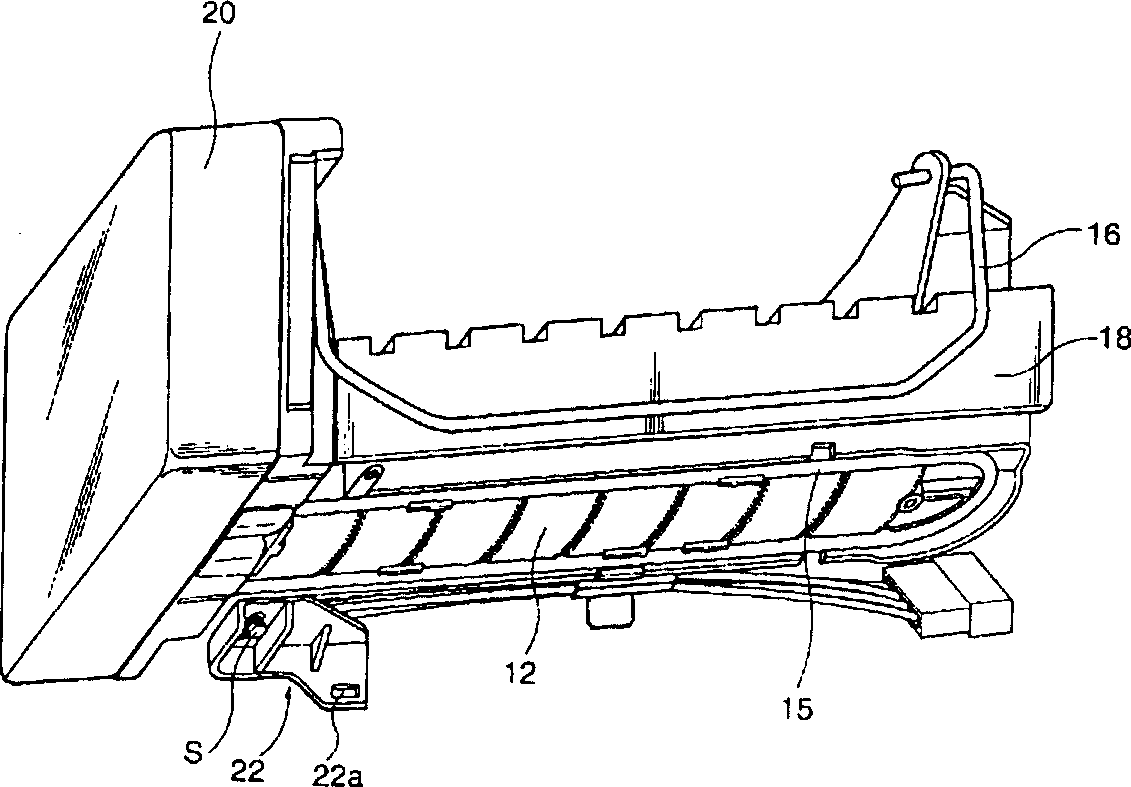
[0022] As previously mentioned, the heater 15 in the ice maker is used only during the ice pushing action. That is to say, starting the heater 15 just means the start of the ice pushing action, and stopping the heating of the heater 15 means the end of the ice pushing action. Therefore, the on-off control process of the heater 15 in the present invention will be described together with the mechanical structure of the ice pushing action.
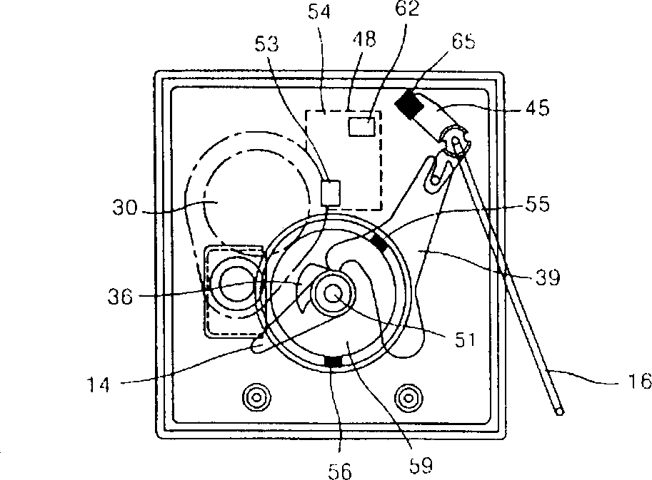
[0023] like figure 2 As shown, the motor 30 is the power device of the ice maker, and in addition to providing power for the rotation of the ice pushing rod 14, it also provides power for the cam 36 that detects full ice.
[0024] In order to sense the position of the ice ejector bar 14, a first magnet 56 is installed on one side of the gear 59 driven by the motor 30, and a first sensor 53 for sensing the first magnet 56 is installed on the control board 48, pushing The ice bar 14 is then coaxially installed on the rotating shaft 51 of the...
PUM
 Abstract
Description
Claims
Application Information
 - R&D Engineer
- R&D Manager
- IP Professional
- Industry Leading Data Capabilities
- Powerful AI technology
- Patent DNA Extraction
Browse by: Latest US Patents, China's latest patents, Technical Efficacy Thesaurus, Application Domain, Technology Topic, Popular Technical Reports.
© 2024 PatSnap. All rights reserved.Legal|Privacy policy|Modern Slavery Act Transparency Statement|Sitemap|About US| Contact US: help@patsnap.com