Electronmagnetic clutch

An electromagnetic clutch and electromagnetic force technology, which is applied in clutches, magnetic drive clutches, non-mechanical drive clutches, etc., can solve the problems of a large number of components and a large number of man-hours in electromagnetic clutches, and achieve the effect of reducing impact and reducing operating noise

Inactive Publication Date: 2003-09-10
DENSO CORP
View PDF1 Cites 14 Cited by
  • Summary
  • Abstract
  • Description
  • Claims
  • Application Information

AI Technical Summary

Problems solved by technology

However, there is also a problem that the electromagnetic cl

Method used


Image

  • Electronmagnetic clutch
  • Electronmagnetic clutch
  • Electronmagnetic clutch

Examples


no. 2 example

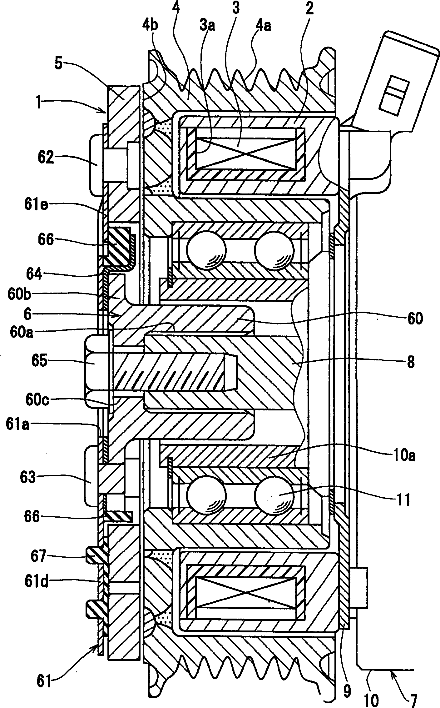
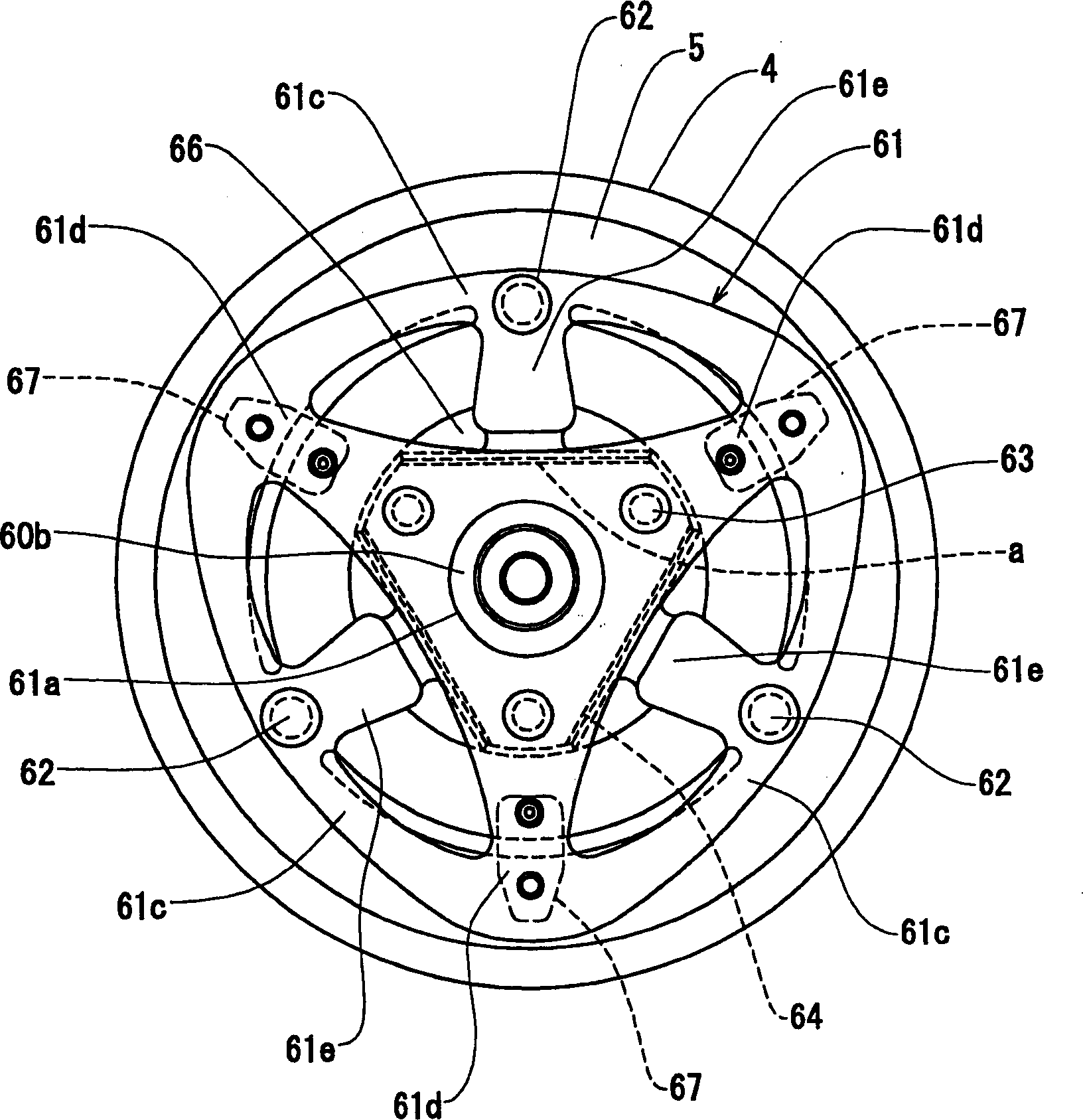
[0072] In the first embodiment described above, the first elastic member 67 and the second elastic member 66 are both separate elements, but the first elastic member 67 and the second elastic member 66 may be integrated. By referring to FIGS. 9 to 11, the second embodiment will be explained. Reference attached Figure 9A with 9B According to the second embodiment, the second elastic member 66 is provided with three integrally formed protrusions 67 which are located at the midpoint in the circumferential direction between the D-shaped elastic members 66a on the second elastic member, and Extend radially outwards.

[0073] Such as Picture 10 with 11 As shown, these protruding parts 67 are arranged between the armature 5 and the leaf spring 61, and are positioned at the midpoint between the fixed parts 62, so as to provide an initial offset for the leaf spring 61, which is equivalent to that in the first embodiment. The first elastic member 67. Therefore, the reduction in the number...


PUM


Abstract

An electromagnetic clutch reduces clutch operating noise at a low cost by utilizing elastic members which are suited to a spring force of a leaf spring. An approximate nonagonal leaf spring has an outer ring portion, attachment portions connected to a hub, and connecting portions. Under the outer ring portion, securing portions of an armature are disposed. First elastic members are disposed at intermediate points of the securing portions, and a second elastic member is disposed in a gap between the leaf spring and the hub along an axial direction. When actuating the electromagnetic clutch, the leaf spring compresses the second elastic member, and when stopping the electromagnetic clutch, the armature collides with the first elastic member so that an axial position of the armature is secured.

Description

Technical field [0001] The present invention relates to an electromagnetic clutch for transmitting and stopping rotational force. In particular, the present invention relates to reducing the running noise generated when the electromagnetic clutch is started and stopped. Background technique [0002] A type of electromagnetic clutch is disclosed in Japanese Patent Publication No. 2000-179582. This patent application includes an armature that is attracted to a rotating member on the driving side by an electromagnetic force generated by an electromagnetic coil, and a slave connected to a rotating device on the driven side. The rotating side member and a piece of annular leaf spring serve as a spring device for connecting the armature and the main rotating side member. [0003] The ring-shaped leaf spring includes an outer ring part connected to the armature, arranged in the outer ring part and connected to the joining part of the turning side member, connected between the outer ring...

Claims


Application Information

Patent Timeline
IPC IPC(8): F16D27/112F16D27/14
CPCF16D27/112F16D2027/007F16D27/14F16D27/10
Inventor 林敏弘
Owner DENSO CORP
Why Eureka
Try Eureka