
Vapor-liquid separation type two-phase liquid separator

A vapor-liquid separator and vapor-liquid separation technology, applied in refrigeration and liquefaction, refrigeration components, refrigerators, etc., can solve the instabilities and uncertainties that are difficult to ensure uniform liquid separation of two-phase flow, and reduce the design efficiency of air conditioners and other problems, to achieve the effect of smaller pressure drop, smaller flow resistance, and smaller suction specific volume.

Inactive Publication Date: 2003-09-10
SHANGHAI JIAO TONG UNIV
View PDF0 Cites 6 Cited by
  • Summary
  • Abstract
  • Description
  • Claims
  • Application Information

AI Technical Summary

Problems solved by technology

The disadvantage of this type of liquid separator is that it is difficult to ensure the uniform liquid separation of the two-phase flow (because the local flow of the two phases has strong instability and uncertainty), often through a large number of experiments to improve or verify its performance, Reduced air conditioner design efficiency

Method used


Image

  • Vapor-liquid separation type two-phase liquid separator
  • Vapor-liquid separation type two-phase liquid separator

Examples


Embodiment Construction

[0009] The technical solutions of the present invention will be further described below in conjunction with the accompanying drawings and embodiments.

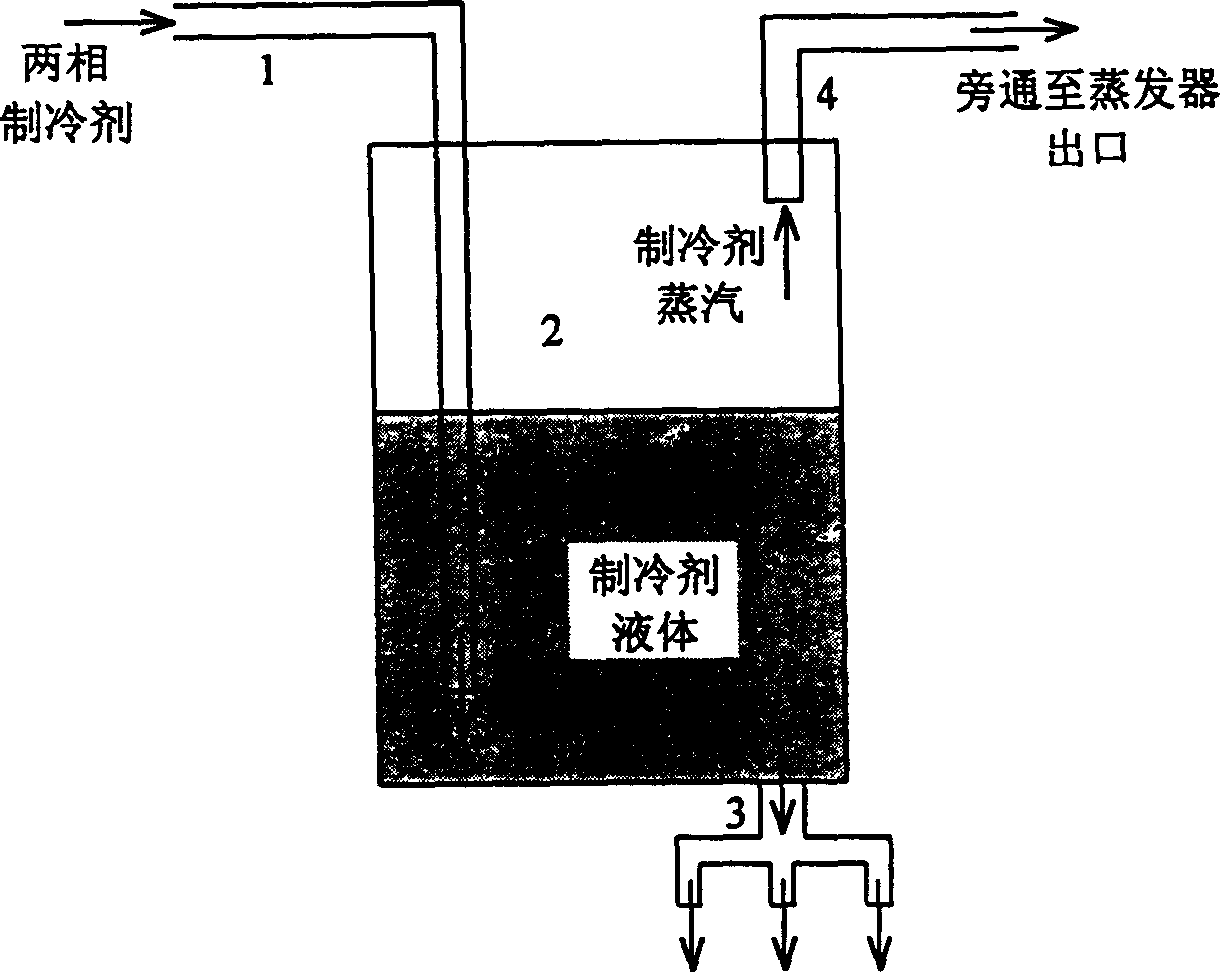
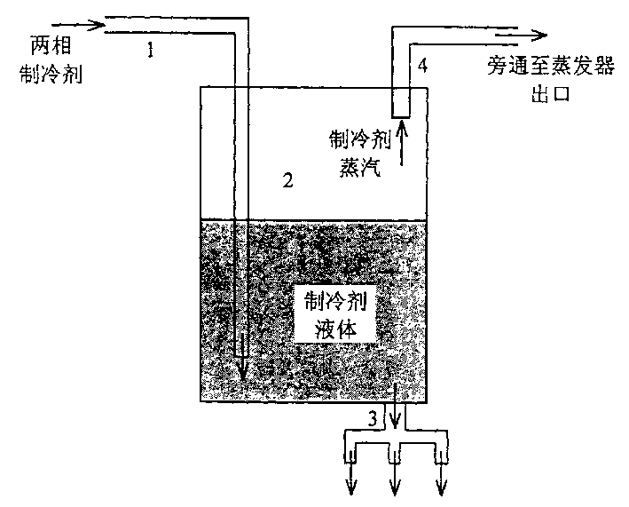
[0010] Such as figure 1 As shown, the present invention mainly includes a liquid inlet pipe 1 , a vapor-liquid separator 2 , a liquid separator 3 , and a steam bypass pipe 4 . The gas-liquid separator 2 is placed vertically. The liquid inlet pipe 1 is connected from the upper part of the gas-liquid separator 2 and leads directly to the vicinity of the bottom of the gas-liquid separator 2 . A liquid outlet 3 is installed at the bottom of the vapor-liquid separator 2 . A steam bypass pipe 4 is installed on the top of the vapor-liquid separator 2 .

[0011] The flow splitting process of the refrigerant is as follows: the low-quality vapor-liquid two-phase refrigerant from the throttling device flows into the gas-liquid separator 2 from the liquid inlet pipe 1, the refrigerant undergoes vapor-liquid separation under the action ...


PUM


Abstract

The vapor-liquid separation type two-phase liquid separator includes mainly liquid inlet pipe, vertical vapor-liquid separator, liquid separating port and vapor bypass tube. The liquid inlet pipe enters the vapor-liquid separator from its upper part and reaches its bottom. The vapor-liquid separator has liquid separating port installed on the bottom and vapor bypass tube installed in the top. In the present invention, the two phase flow is first vapor-liquid separately, only the separated refrigerant is then divided, and the separated refrigerant vapor in bypassed directly to the outlet of the evaporator. Unlike traditional two-phase liquid separator, which has flow rate distribution affected by the instability and uncertainty of the two-phase flow, the present invention has high design efficiency of air conditioner. In addition, the decrease of evaporator flow rate is favorable to raising energy efficiency of the air conditioner.

Description

Technical field: [0001] The invention relates to a two-phase liquid divider, in particular to a two-phase flow divider used in an evaporator of an air conditioner, which is used for controlling the flow distribution of refrigerant in the evaporator, and belongs to the technical field of refrigeration. Background technique: [0002] The evaporator of the air conditioner generally adopts a split structure, that is, after the refrigerant enters the evaporator, it is divided into several parallel paths for heat exchange, and finally merged into one path, and enters the compressor through the suction pipe. Therefore, a liquid separator is required to complete the flow distribution of the refrigerant among the branches of the evaporator. Since the liquid refrigerant coming out of the condenser generally passes through the throttling device before entering the liquid separator of the evaporator, the liquid refrigerant has been flashed into a vapor-liquid two-phase fluid. The refri...

Claims


Application Information

Patent Timeline
Patent Type & Authority Applications(China)
IPC IPC(8): F25B43/00
Inventor 张春路丁国良
Owner SHANGHAI JIAO TONG UNIV
Learn More