

Suction pressure structure of cone-shaped spring in ink box
A conical spring and ink cartridge technology, applied in the field of negative pressure structure, can solve the problem that the air bag cannot be effectively used
- Summary
- Abstract
- Description
- Claims
- Application Information
AI Technical Summary
Problems solved by technology
Method used
Image

Examples
no. 1 example
[0043] In this embodiment, the conical spring 20 is arranged in the ink-holding space 10 to respond to the pressure change between the ink-holding space 10 and the external environment, so that there is a constant negative pressure value between the ink-holding space 10 and the external environment. see Figure 9-1 As shown, it is a structural schematic view of the first embodiment of the present invention. The conical spring negative pressure structure includes an ink holding space 10, a conical spring 20 inside, an air bag 31 on one side of the conical spring 20 and The pressure plate 21 located between the above-mentioned elements; wherein the conical spring 20 is a conical compression spring, and the neck 33 of the air bag 31 is provided with an air inlet 32 communicating with the external environment, and the air inlet 32 makes the external air The meat of the air bag 31 can be entered to expand the air bag 31; one end of the conical spring 20 is fixed on the wall of ...
no. 2 example
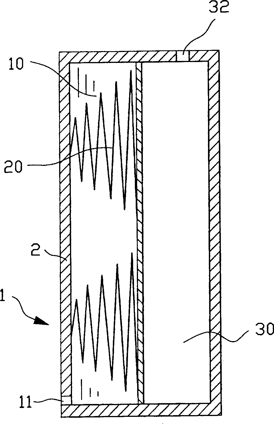
[0047] In this embodiment, the conical spring 20 is set in the ink holding space 10 and has two air pockets 31, please refer to Figure 10-1 As shown, it is a structural schematic diagram of the second embodiment of the present invention. The conical spring negative pressure structure includes an ink holding space 10, a conical spring 20 inside it, and two air bags located on both sides of the conical spring 20. 31; wherein the two air bags 31 are connected and have an air inlet 32, when the amount of ink in the ink holding space 10 decreases, the gas enters the air bag 31 from the air inlet 32, so that the two air bags The volume of the bag 31 expands, and the conical spring 20 moves along its axial direction at the same time. When the conical spring 20 reaches the equilibrium position, the predetermined negative pressure value is reached between the ink holding space 10 and the external environment, and when the two air bags 31 When the volume expands to the maximum, the con...
no. 3 example
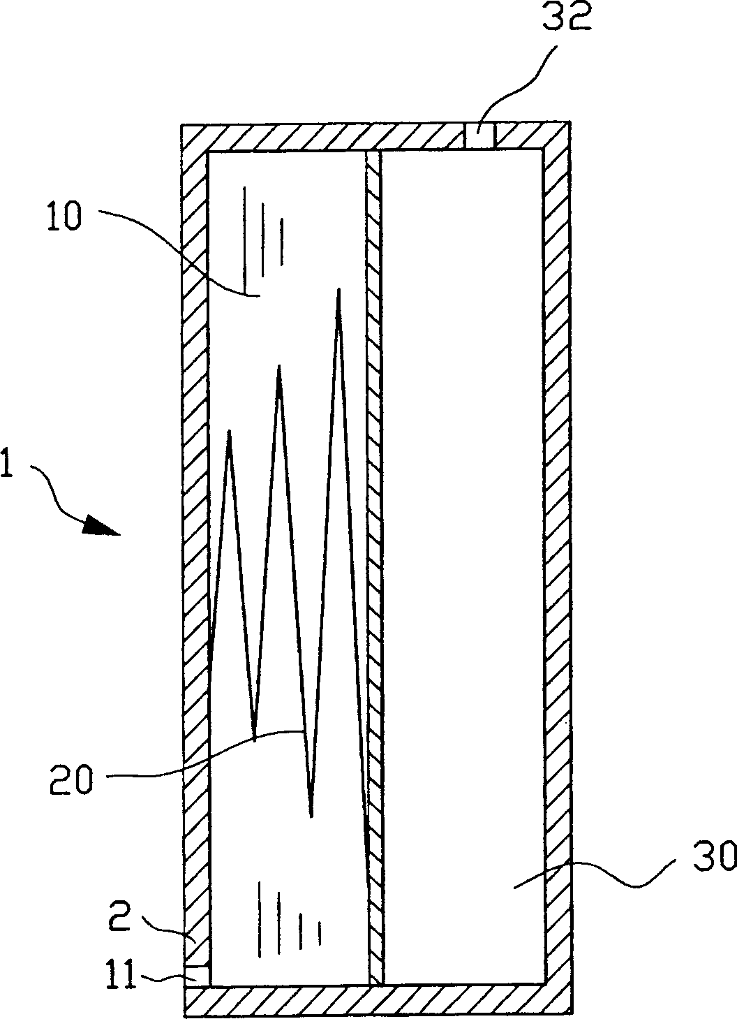
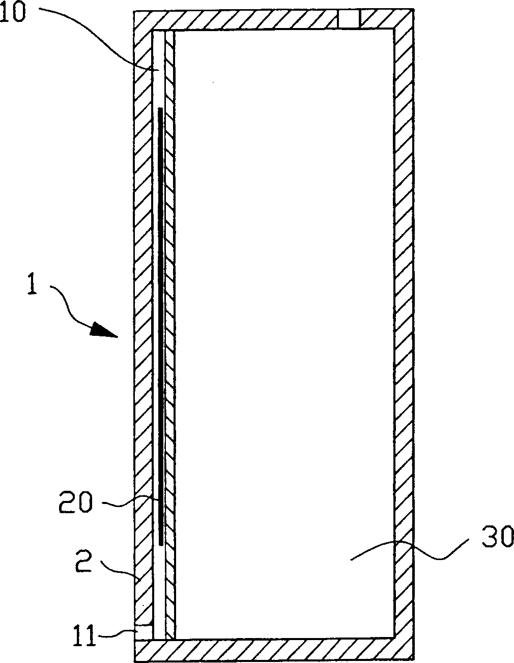
[0050] In this embodiment, the conical spring 20 is arranged in the atmospheric space 30, so as to respond to the pressure change between the ink containing space 10 and the atmospheric space 30, so that there is a constant negative pressure value between the ink containing space 10 and the atmospheric space 30 , see Figure 11-1 and Figure 11-2 As shown, it is a schematic view of the structure of the third embodiment of the present invention and a schematic view of the action of the third embodiment of the present invention to the final position. The conical spring negative pressure structure includes an ink holding space 10 and is located in the ink holding space 10. The air bag 31 on one side, the conical spring 20 that is located in the air bag 31; Wherein the neck 33 of this air bag 31 is provided with an air inlet 32 that communicates with the external environment, and the air inlet 32 makes outside air can enter air In the bag 31, the air bag 31 is expanded; the c...
PUM
 Abstract
Description
Claims
Application Information