Pivot set

A pivot and bushing technology, which is applied in the field of pivot devices, can solve the problems that users are difficult to separate the pivot portion 110 from the pivot groove, and the casing 102 and the flip cover 104 are discarded and wasted.

Inactive Publication Date: 2003-10-08
BENQ CORP
View PDF0 Cites 0 Cited by
  • Summary
  • Abstract
  • Description
  • Claims
  • Application Information

AI Technical Summary

Problems solved by technology

Because the casing 102, the pivot groove 114, the pivot holes 116a and 116b are integrally formed, and the flip cover 104, the pivot portion 110, and the pivot pins 112a and 112b are also integrally formed, causing the user to assemble the machine It seems quite strenuous when the shell 102 and the cover 104 are lifted
Wherein, when the user wants to repair the mobile phone 100, since the pivot bolts 112a and 112b are tightly fitted with the pivot holes 116a and 116b after being assembled respectively, the user must separate the casing 102 from the flip cover 104 before repairing the mobile phone 100. Repairable, and it is difficult for users to separate the pivot portion 110 from the pivot groove 114
If the user can separate the casing 102 and the flip cover 104, the structure of the pivot portion 110 and the pivot groove 114 will also be damaged, so that the damaged casing 102 and the flip cover 104 will not be usable and will be discarded. seems very wasteful

Method used


Image

  • Pivot set
  • Pivot set
  • Pivot set

Examples


Embodiment Construction

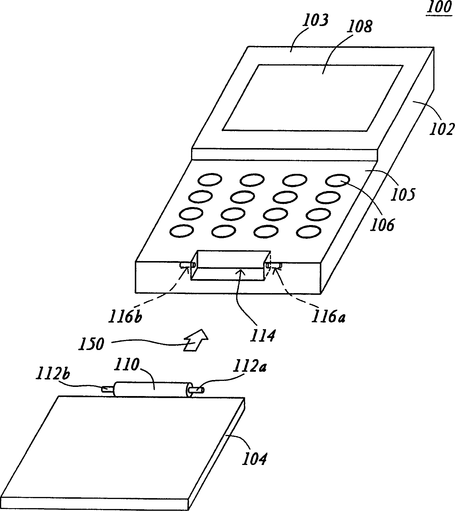
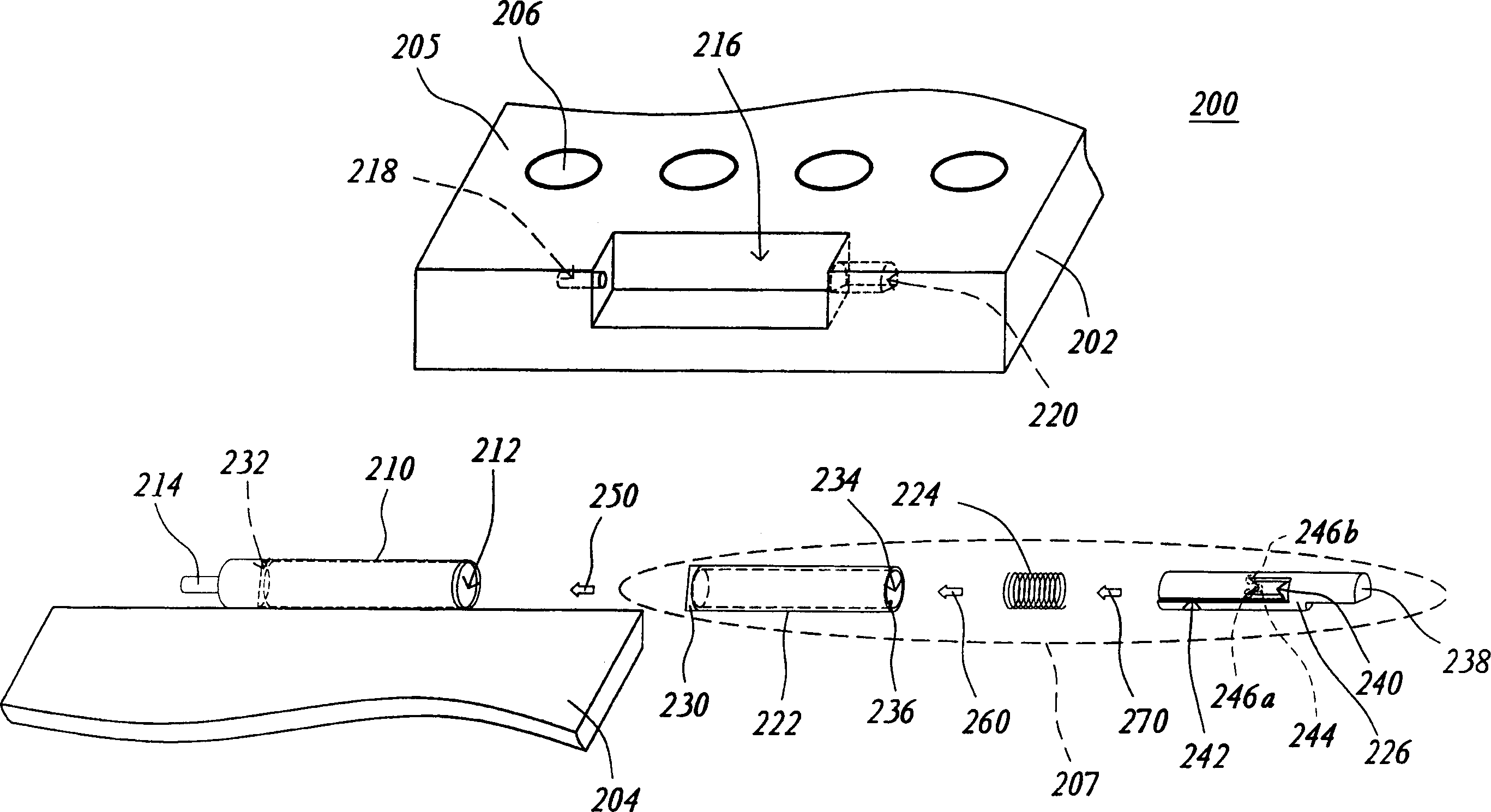
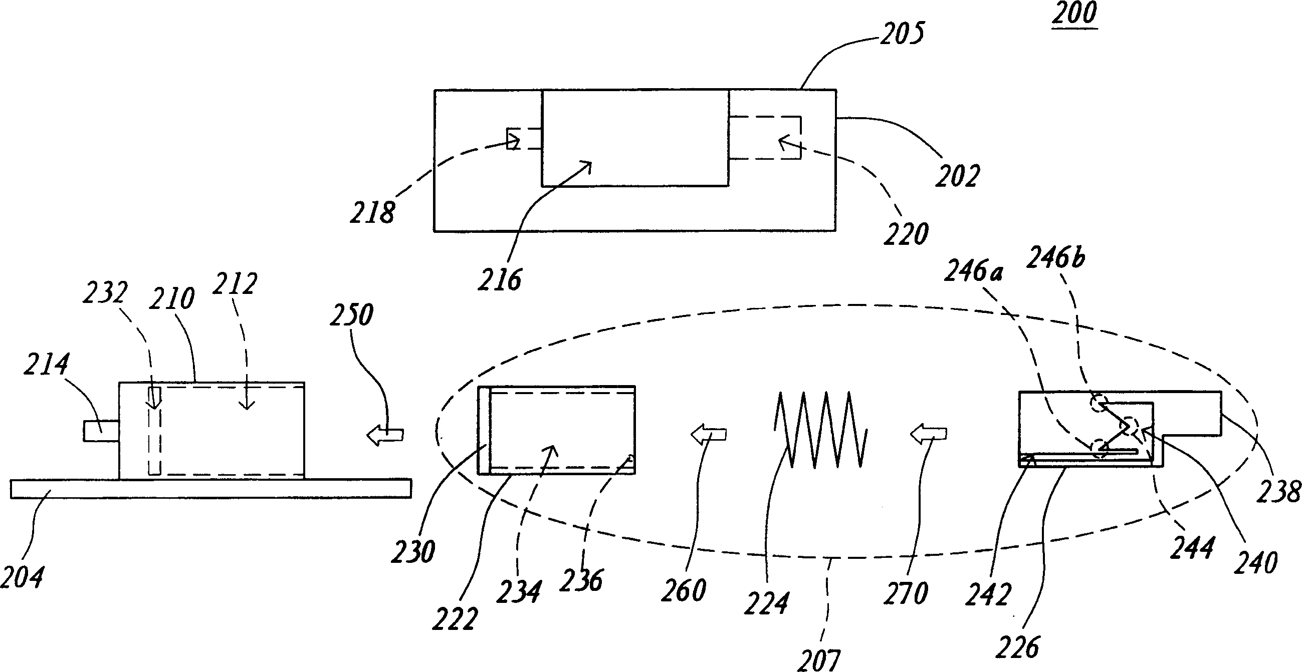
[0020] The present invention specially designs a hinge device (Hinge Device) 207, which is used to connect a flip cover (Flip) 204 and a casing (Housing) 202 of a foldable device, so that the flip cover can be arranged on the machine in an openable and closable manner. on the shell. Wherein, the pivot device includes a bush, a spring and a camshaft. Wherein, the bushing is buckled in the flip cover, and the bushing has a bushing hollow groove and an inner protrusion, and the inner protrusion is arranged on the groove wall of the bushing hollow groove. In addition, the spring is used to be arranged in the hollow groove of the bushing, and one end of the camshaft is used to be arranged in the hollow groove of the bushing, so that the two ends of the spring are respectively against the bottom of the camshaft and the hollow groove of the bushing, and the other end of the camshaft One end is buckled in the casing, and the outer side of the camshaft has a cam groove for coupling wi...


PUM


Abstract

The pivot set connected to the lift cover and the case includes the bushing the springs and the camshaft. The bushing is clip connected to the lift cover. The bushing possesses the dead slot and inner root object setup at the wall of the bushing dead slot one end of the camshaft through a spring is setup at the dead slot and another end is in clip connection with the case. The cam groove located at outside the releasuring button is coupled to the inner root object. When the lift over is going to open or close, the bushing is rotated synchronistically. The inner root object generates the movement relative to the cam groove making the camshaft transverse in the bushing dead slot.

Description

technical field [0001] The invention relates to a hinge device, in particular to a hinge device designed on the premise of the relative movement between a bushing and a camshaft. Background technique [0002] With the frequent communication of information among the masses, the mobile phone (Cellular Phone) has become an indispensable tool for modern people. Its small size and easy to carry feature make people can communicate with others through it anytime and anywhere, which is much more convenient and in line with modern People stress time and strive for efficiency needs. [0003] Please refer to figure 1 , which shows an exploded schematic diagram of a general foldable mobile phone. exist figure 1 Among them, the mobile phone 100 includes a casing 102 and a flip cover 104, and the casing 102 includes a display plane 103, an operation plane 105, several buttons 106 and a liquid crystal display panel (Liquid Crystal Display, LCD) 108, and the disp...

Claims


Application Information

Patent Timeline
Patent Type & Authority Applications(China)
IPC IPC(8): F16C11/00H04M1/02H05K7/16
Inventor 潘隆智陈效吾
Owner BENQ CORP
Why Eureka
Try Eureka