Plate holding apparatus

A technology of clamping equipment and plate clamps, which is applied in printing, printing machines, printing processes, etc., and can solve problems such as damage to the printing plate cylinder and breakage of the printing plate clamping device

Inactive Publication Date: 2003-10-22
KOMORI CORP
View PDF1 Cites 7 Cited by
  • Summary
  • Abstract
  • Description
  • Claims
  • Application Information

AI Technical Summary

Problems solved by technology

In this example, the plate is bent so that the plate does not come off the plate cylinder, correspondingly, the elastic restoring force of the plate may break the plate clamping mechanism, which is not desired
Deformed plates can also get into the inker rollers, come into reverse contact and damage the plate cylinder, which is also not desirable

Method used


Image

  • Plate holding apparatus
  • Plate holding apparatus
  • Plate holding apparatus

Examples


Embodiment Construction

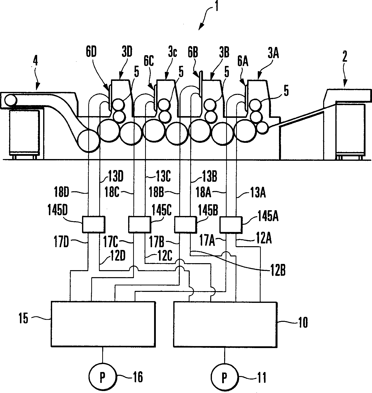
[0041] According to one embodiment of the present invention, reference will be made to Figures 1 to 29 Describe a plate holding device. Such as figure 1 As shown, a sheet-fed rotary printing machine 1 includes a feeder 2 for feeding paper, printing units 3A to 3D for printing four different colors on the incoming paper, and a printing unit for stacking Output unit 4 for paper coming out of printing unit 3D. A plate cylinder 5 is rotatably fixed by a pair of opposing frames, and a printing plate is mounted thereon, and each of the printing units 3A to 3D is equipped with a plate cylinder 5 . Safety covers 6A to 6D are mounted as movable members on output sides of the printing units 3A to 3D, respectively. The safety covers 6A to 6D are respectively supported by the printing units 3A to 3D so that they can be moved vertically by air cylinders 30 . When each safety cover 6A to 6D is moved upward, the safety cover opens the front portion of the corresponding plate cylinder 5 ...


PUM


Abstract

A plate holding apparatus includes a plate holding device (40A,40B) and an air cylinder (41). The plate holding device holds an old plate (25A) discharged from a plate cylinder (5). The air cylinder (41) moves the plate holding device between the first position of holding the discharged old plate and the second position away from the plate cylinder. The plate holding device includes a support member (42), first (43) and second (44) rotary members, a lever (64), stopper (69), and tensile coil spring (71), and a one-way clutch (45,46). The first rotary member is rotatably, axially supported by the support member. The second rotary member is axially supported by the support member to be movable and rotatable. The lever, stopper, and tensile coil spring move the second rotary member to come into contact with and separate from the first rotary member. When the old plate is held by the first and second rotary members, the one-way clutch allows at least one of the first and second rotary members to rotate in the first direction to disengage the old plate from the plate cylinder, and regulates it from rotating in the second direction opposite to the first direction.

Description

technical field [0001] The invention relates to a printing plate clamping device for removing old plates from a printing plate cylinder during a printing plate exchange. Background technique [0002] This type of plate clamping apparatus is disclosed in Japanese Patent Publication No. 2000-255031 (Reference 1). The apparatus disclosed in reference 1 consists of a carriage installed in the cassette for collecting old plates, and by means of a drive to enable the carriage to move vertically, a fixed roller axially supported by the carriage, and a A movable roller capable of contacting and disengaging a fixed roller and back contacting the fixed roller by means of a biasing device. When the carriage is in a down position, the movable rollers are separated from the fixed rollers. As the carriage moves forward, the movable rollers are brought into reverse contact with the fixed rollers by the biasing force of the biasing device. [0003] In this structure, when one end of the ...

Claims


Application Information

Patent Timeline
Patent Type & Authority Applications(China)
IPC IPC(8): B41F27/12
CPCB41F27/1206Y10S101/36
Inventor 青木孝畅
Owner KOMORI CORP
Why Eureka
Try Eureka