Monitoring connection to user terminal in telecommuncations system

A technology of user terminals and telecommunication systems, which is applied in the field of monitoring the connection between telecommunication systems and user terminals, can solve problems such as inconsistent billing, and achieve the effect of avoiding possible wrong behaviors

Inactive Publication Date: 2003-10-22
NOKIA NETWORKS OY
View PDF0 Cites 3 Cited by
  • Summary
  • Abstract
  • Description
  • Claims
  • Application Information

AI Technical Summary

Problems solved by technology

However, the problem is that the CSCF may be in an error state for a long time, causing inconsistent billing
In case CFNRc (Call Forwarding Not Reachable) is activated and CFB (Call Forwarding Busy) is not activated, also leads to wrong behavior in CSCF

Method used


Image

  • Monitoring connection to user terminal in telecommuncations system
  • Monitoring connection to user terminal in telecommuncations system
  • Monitoring connection to user terminal in telecommuncations system

Examples


Embodiment Construction

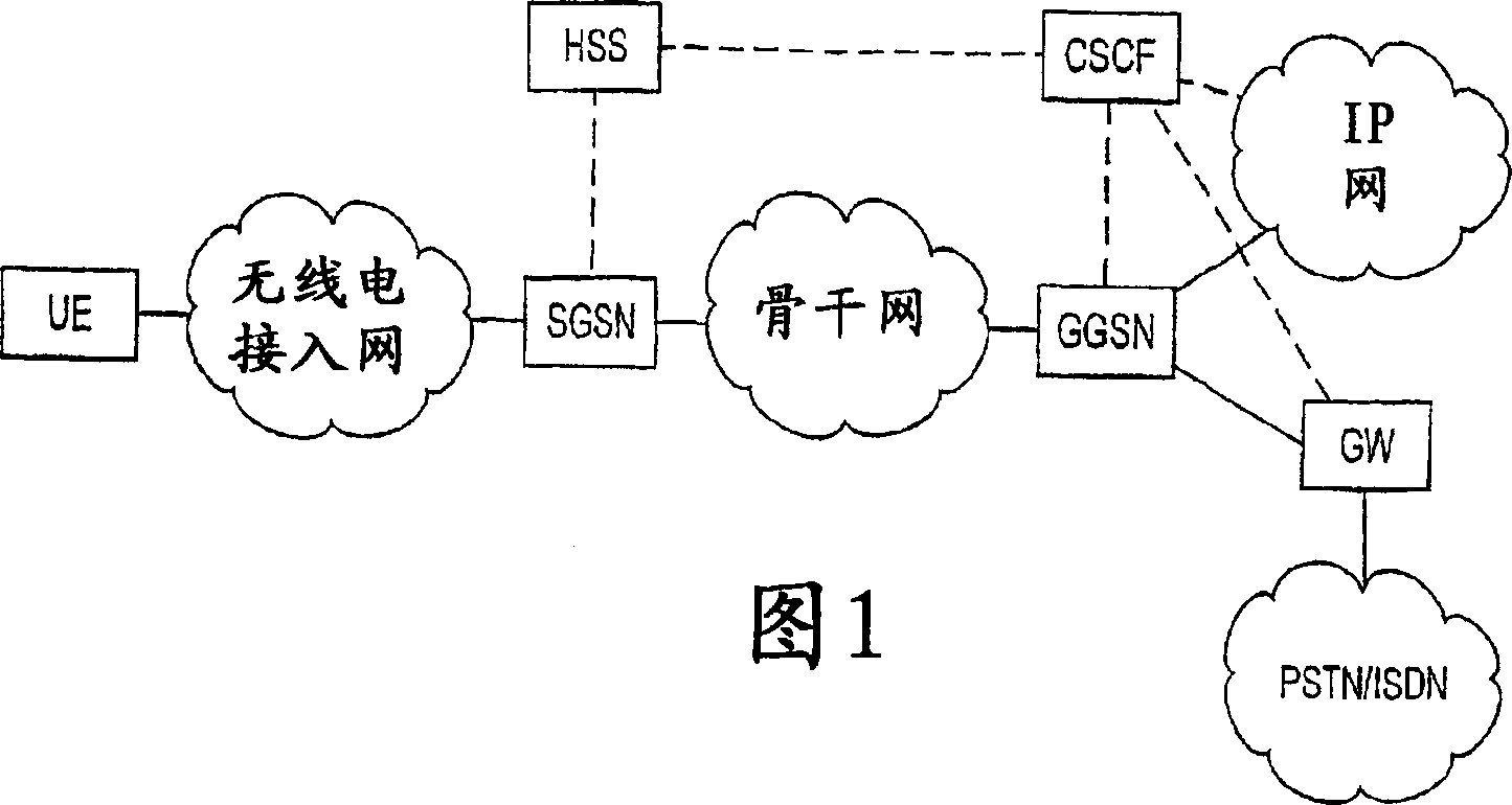
[0018] The present invention can be applied to various telecommunication systems. The systems include third generation mobile communication systems such as UMTS (Universal Mobile Telecommunications System). The present invention will be described below using the 3GPP ALL-IP system, which is the UMTS system based on IP technology and specified within 3GPP (3rd Generation Partnership Project), as an exemplary system, but the present invention is not limited thereto. The technical specifications of mobile communication systems, especially the technical specifications of said third generation mobile communication systems are rapidly developing. Therefore, the present invention may require additional changes. All words and expressions should be interpreted broadly, since they are intended only to describe, not to limit, the invention. The key point of the present invention lies in the functions mentioned, not the network elements where the functions are located.

[0019] Figure ...


PUM


Abstract

The present invention discloses a method for monitoring a connection to a user terminal in a telecommunications system and a telecommunications system comprising an element (CSCF) controlling a connection to a user terminal (UE) and a system part (SGSN, GGSN) providing transport of user data, which system part is separate from said controlling element, wherein a system element which knows the state of the connection to the user terminal (UE) is arranged to send an indication message to the controlling element indicating the state of the connection, and the controlling element (CSCF) is arranged to decide the state of the connection to the user terminal (UE) based on the indication message received.

Description

technical field [0001] The invention relates to monitoring connections to subscriber terminals within a telecommunications system. [0002] The invention can be used in different telecommunication systems, such as the Universal Mobile Telecommunications System (UMTS). In the following the invention will be described by means of embodiments with reference to UMTS, in particular the UMTS system specified within the 3rd Generation Partnership Project 3GPP, but the invention is not limited thereto. Background technique [0003] Figure 1 shows an example of a network architecture of a UMTS system. In this figure, solid lines between different network elements represent signaling and data interfaces, while dashed lines between network elements represent signaling interfaces only. The main parts of the system are the radio access network and the core network for providing access to user terminals UE (User Equipment). In the example of FIG. 1, the core network includes Serving GP...

Claims


Application Information

Patent Timeline
Patent Type & Authority Applications(China)
IPC IPC(8): H04B7/26H04L12/26H04L12/28H04L12/56H04W76/04
CPCH04W76/04H04L43/00H04L12/26H04W76/20
Inventor 海基·爱诺拉劳丽·拉廷恩里斯托·考品恩赛浦·霍塔利
Owner NOKIA NETWORKS OY
Why Eureka
Try Eureka