
Robot vacuum cleaner with air stirring

A technology of vacuum cleaners and air agitation, applied in the direction of vacuum cleaners, robot cleaning machines, suction nozzles, etc., can solve the problems of inability to completely remove pollutants, harmful, unpleasant, etc.

Inactive Publication Date: 2003-10-29
SAMSUNG GWANGJU ELECTRONICS CO LTD
View PDF0 Cites 9 Cited by
  • Summary
  • Abstract
  • Description
  • Claims
  • Application Information

AI Technical Summary

Problems solved by technology

[0004] Conventional robot vacuums sometimes fail to completely remove contaminants, especially those embedded in carpet or stuck to the surface being cleaned
This can be particularly unpleasant and even harmful if fine contaminants such as dust, mites or other allergens remain

Method used


Image

  • Robot vacuum cleaner with air stirring
  • Robot vacuum cleaner with air stirring
  • Robot vacuum cleaner with air stirring

Examples


Embodiment Construction

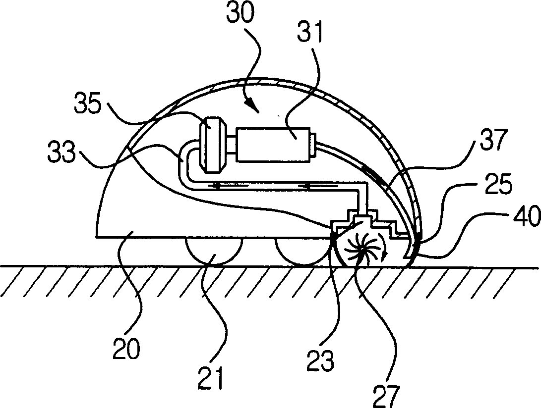
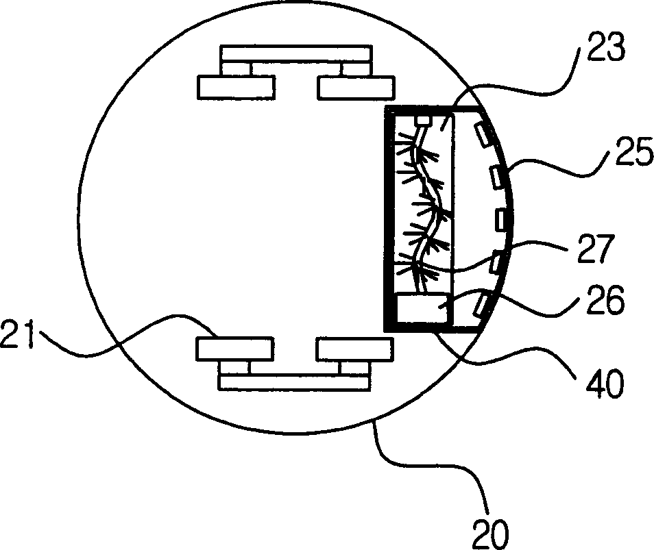
[0013] Embodiments of the present invention will be described below with reference to the accompanying drawings. see figure 2 and 3 The robot vacuum cleaner of the present invention includes a cleaner body 20, an air circulation mechanism 30 provided inside the cleaner body 20, and a seal 40 in addition to known components of a conventional robot vacuum cleaner.

[0014] The cleaner main body 20 automatically runs on the cleaning surface to perform cleaning operations. In order to accomplish this task, the cleaner body 20 has a plurality of wheels 21 provided on its lower part and a suction port 23 through which pollutants and dust are sucked together with air from the cleaning surface. An air injection port 25 or a group of such injection ports is also provided on the underside of the cleaner body 20 adjacent to the suction port 23 . The air injection port 25 is designed to enhance the sweeping operation by providing air agitation to the sweeping surface to aid in the rem...


PUM


Abstract

A robot vacuum cleaner comprising a cleaner main body having wheels provided on a lower part and a suction port through which pollutants are sucked from a cleaning surface; Contaminants are filtered from the contaminated air and then non-contaminated air is injected into the air jets to dislodge the contaminants from the surface to be swept. The air injection port is adjacent to the suction port; and the two elements are surrounded by a seal for sealing the area between the sweeping surface and the cleaner body to prevent dislodged contaminants from being dispersed outward.

Description

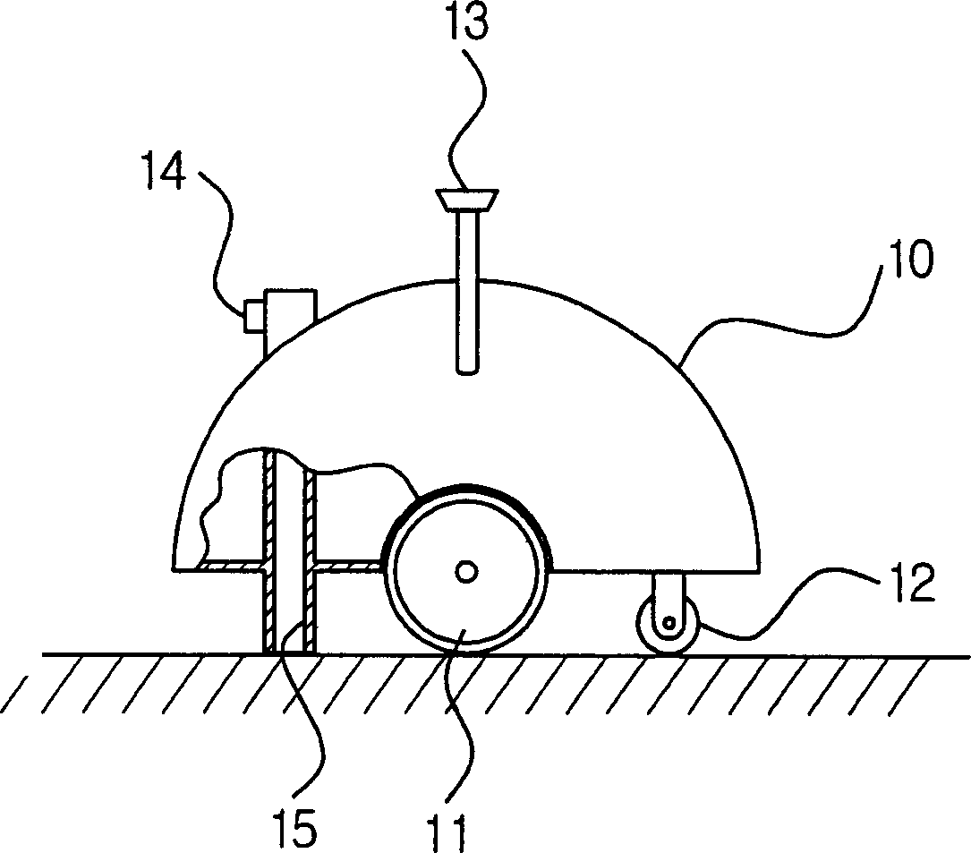
technical field [0001] The present invention relates to a robotic vacuum cleaner, and more particularly to such a robotic vacuum cleaner provided with agitation to clean a surface by means of a jet of air directed towards the surface and the action of agitating the brushes. Background technique [0002] When a robotic vacuum cleaner operates autonomously over an area without being manually guided by a user, it typically sucks in contaminants such as dust from the surface being cleaned. The robotic vacuum cleaner detects obstacles such as furniture, appliances, or walls in the cleaning area by a distance detector relative to its position. The robot vacuum cleaner selectively drives the right wheel motor and / or the left wheel motor to automatically change its direction of travel, thereby performing sweeping operations in the sweeping area. [0003] Such as figure 1 As shown, a conventional robot vacuum cleaner includes a cleaner body 10 , a driving wheel 11 and a driven whee...

Claims


Application Information

Patent Timeline
Patent Type & Authority Applications(China)
IPC IPC(8): A47L9/28A47L5/14A47L9/00A47L9/04A47L9/08A47L11/00
CPCA47L5/14A47L9/009A47L9/04A47L9/08A47L2201/00A47L11/00
Inventor 宋贞坤高将然宋化圭申东烈瓦列里·克拉斯诺斯洛博采夫
Owner SAMSUNG GWANGJU ELECTRONICS CO LTD
Learn More