Wide cut-off band narrow-band filter

A narrow band filter and band gap technology, applied in the field of optical filter devices, can solve the problems of unavailable filter devices, difficulty, high cut-off band, etc., and achieve the effect of broad application prospects

Inactive Publication Date: 2003-11-12
TONGJI UNIV
View PDF0 Cites 4 Cited by
  • Summary
  • Abstract
  • Description
  • Claims
  • Application Information

AI Technical Summary

Problems solved by technology

As a result, there is a contradiction between wide cut-off band and high peak transmission.
[0007] In the traditional structure, it is difficult to obtain both a high transmission peak and a wide cut-off band at the same time, so that an optical filter device with excellent performance working in a wide wavelength range cannot be obtained

Method used


Image

  • Wide cut-off band narrow-band filter
  • Wide cut-off band narrow-band filter
  • Wide cut-off band narrow-band filter

Examples


Embodiment Construction

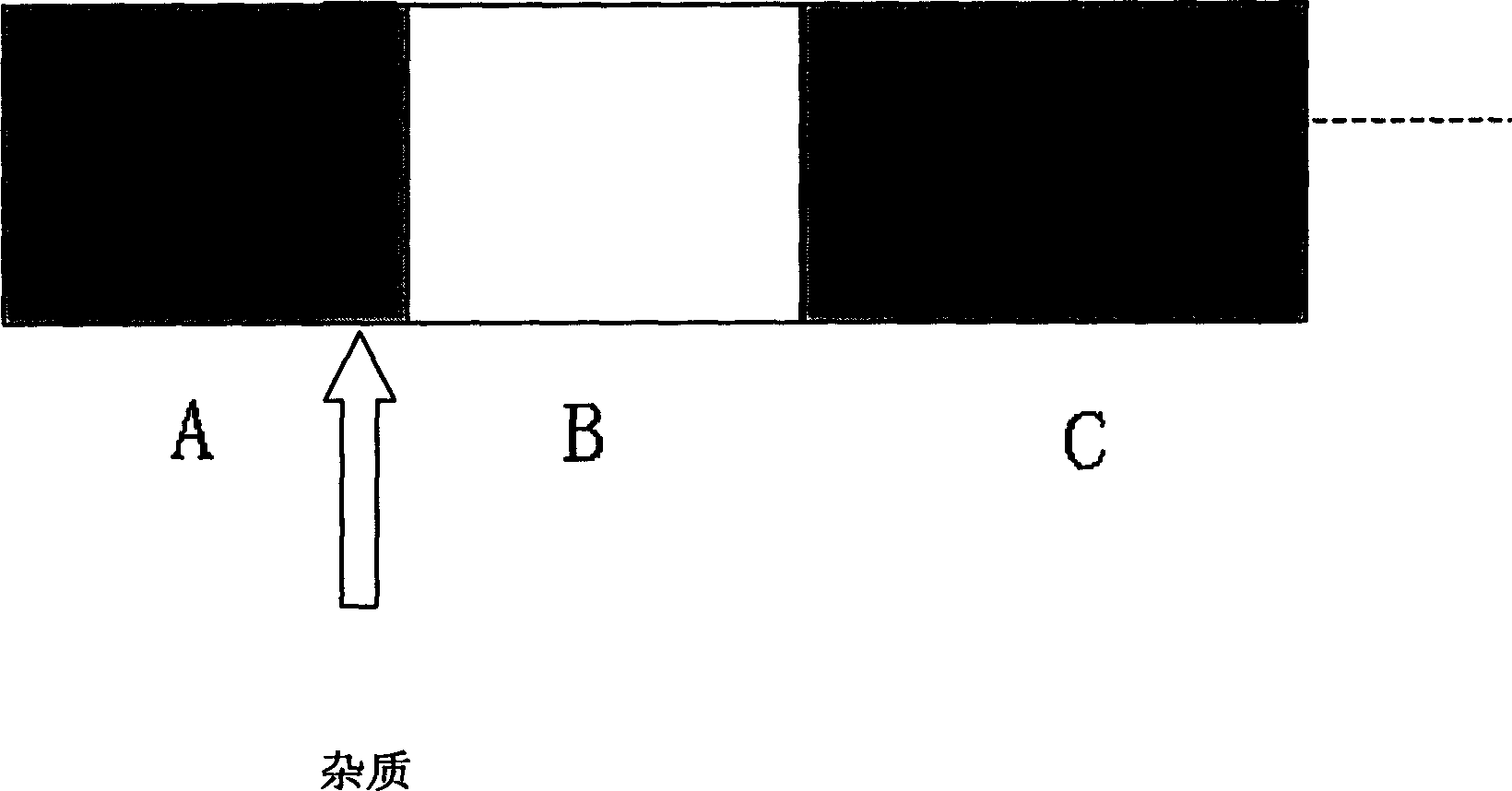
[0022] The method of the present invention's design wide cut-off band filter is as follows:

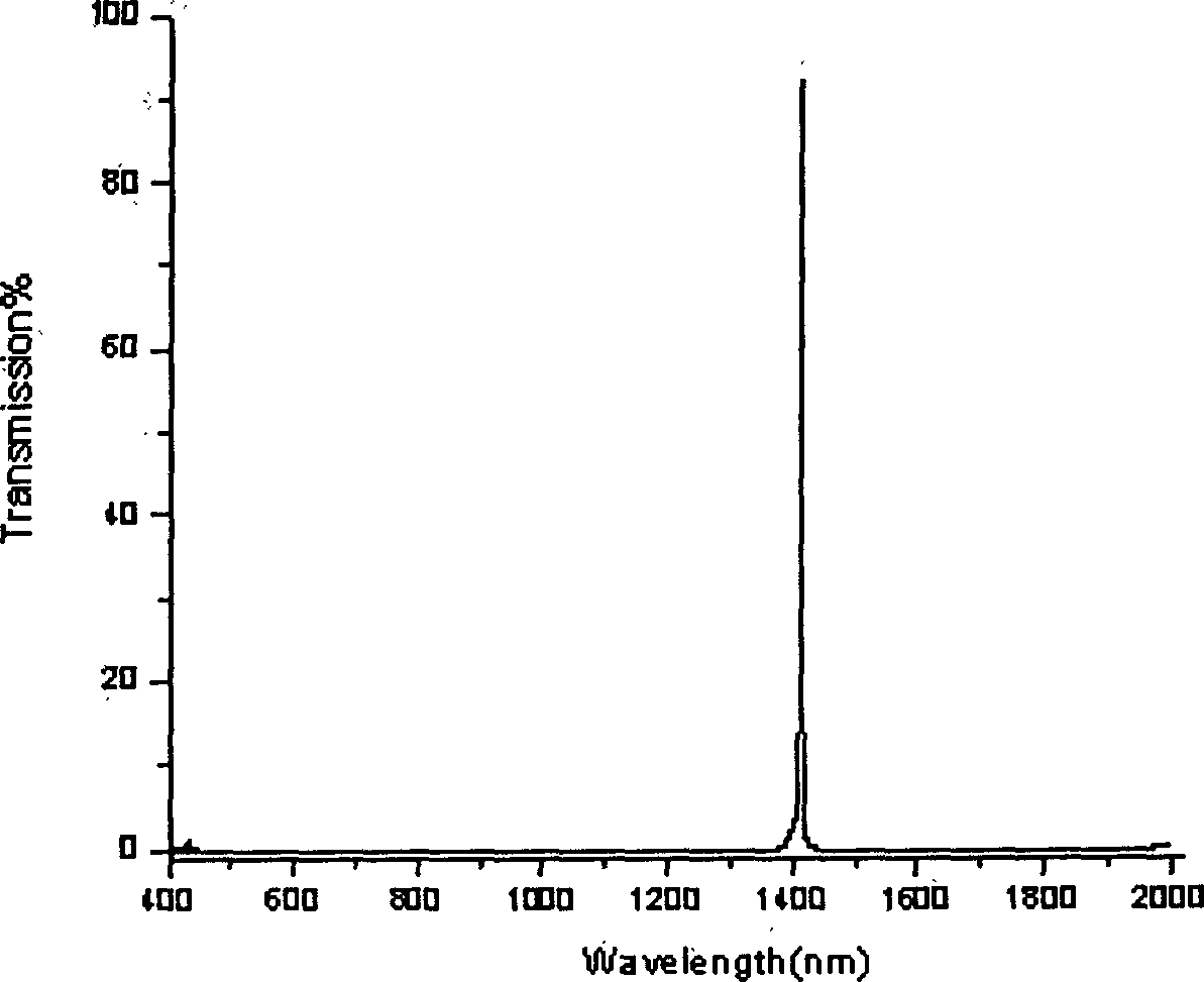
[0023] Materials can be selected according to actual conditions. We choose ZnS, MgF 2 , the incident medium is air ε=1, there is a narrow transmission peak in the wavelength range of 400nm-2000nm, ZnS, MgF 2 The composed medium pair is impurity. Using the transfer matrix method, by adjusting the position and size of the impurity, an ultra-wide ultra-wide band with a peak position of 1413.8nm, a transmittance greater than 80%, a half width of less than 2nm, and a background transmittance of less than 0.5% is obtained. Cut-off band narrow band filter, its transmittance curve is as follows figure 2 As shown, the corresponding structure is:

[0024] (0.6H 0.6L) 3 (0.7H 0.7L) 12 (0.8H 0.8L) 12 (0.9H 0.9L) 12 (1H 1L) 12 (1.2H 1.2L) 12 (1.4H1.4H) 12 (1.6H 1.6L) 12 (1.8H 1.8L) 12 (4.8H 5L) 1 (2.4H 2.4L) 14 (2.6H 2.6L) 9

[0025] Among them: H, L, respectively, the 1 / 4 wavelen...


PUM


Abstract

The invention discloses the narrow band filter using 1D adulteration heterojunction structure possessing super wide cut-off band. Different from the traditional narrow band filter, the invented filter can obtain high peak value of transmittance and the wide cut-off band on the two ends of the peak. The invention introduces the thoughts of designing the filter and the concrete structural design as well as the optical performances of the narrow band filter calculated under the design thoughts. The designed filter can be applicable to optical analysis instruments and optical detection instruments etc.

Description

technical field [0001] The invention relates to an optical filter device, in particular to a wide cut-off band and narrow band filter. Background technique [0002] Traditional narrowband filters generally have the following two types: [0003] 1. Interference cut-off filter [0004] The most typical narrow-band filter is Fabray---Perot interference filter, which is a symmetrical structure with reflective layers at both ends and a spacer layer in the middle. After multiple reflections from the reflective layer, this structure can be obtained A filter with a narrow transmission band, but since the all-dielectric multilayer reflective coating is only effective in a limited area, there will be bypass bands on both sides of the transmission peak of this filter. Therefore, it does not have a wide cut-off band on either side of its transmission peak. [0005] 2. Metal induction filter [0006] The metal-induced filter also has a symmetrical structure. It is mainly a narrow-ban...

Claims


Application Information

Patent Timeline
Patent Type & Authority Applications(China)
IPC IPC(8): G02B5/20G02F1/01
Inventor 王利王占山吴永刚
Owner TONGJI UNIV
Why Eureka
Try Eureka