Light source device

A technology of light source device and optical axis, applied in the direction of light source, electric light source, signal device, etc., can solve the problem that the miniaturization of lamps cannot be greatly realized, and achieve the effect of realizing miniaturization, reducing size and improving strength

Inactive Publication Date: 2003-11-19
KOITO MFG CO LTD
View PDF5 Cites 32 Cited by
  • Summary
  • Abstract
  • Description
  • Claims
  • Application Information

AI Technical Summary

Problems solved by technology

[0007] From this, it can be seen that there is a problem that the conventional projection-type automotive lamps cannot realize the miniaturization of the lamps to a large extent.

Method used


Image

  • Light source device
  • Light source device
  • Light source device

Examples


Embodiment Construction

[0045] Embodiments of the present invention will be described below using the drawings.

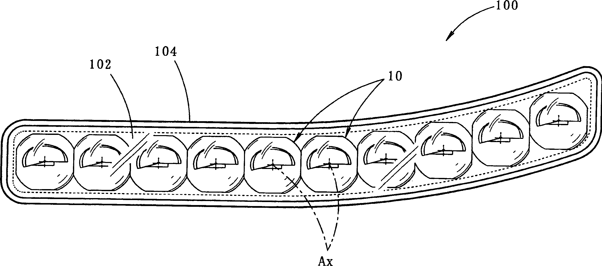
[0046] figure 1 It is a front view showing a vehicle lamp 100 provided with a light source device 10 according to an embodiment of the present invention.

[0047] The vehicular lamp 100 is a headlamp for short-light irradiation, and ten light source devices 10 are placed in a row in a lamp chamber formed by a transparent transparent cover 102 and a lamp body 104 .

[0048] The respective light source devices 10 each have the same structure, and are placed with their optical axis Ax extending in the vehicle front-rear direction (specifically, in a downward direction at about 0.5 to 0.6° with respect to the vehicle front-rear direction). In the lamp room.

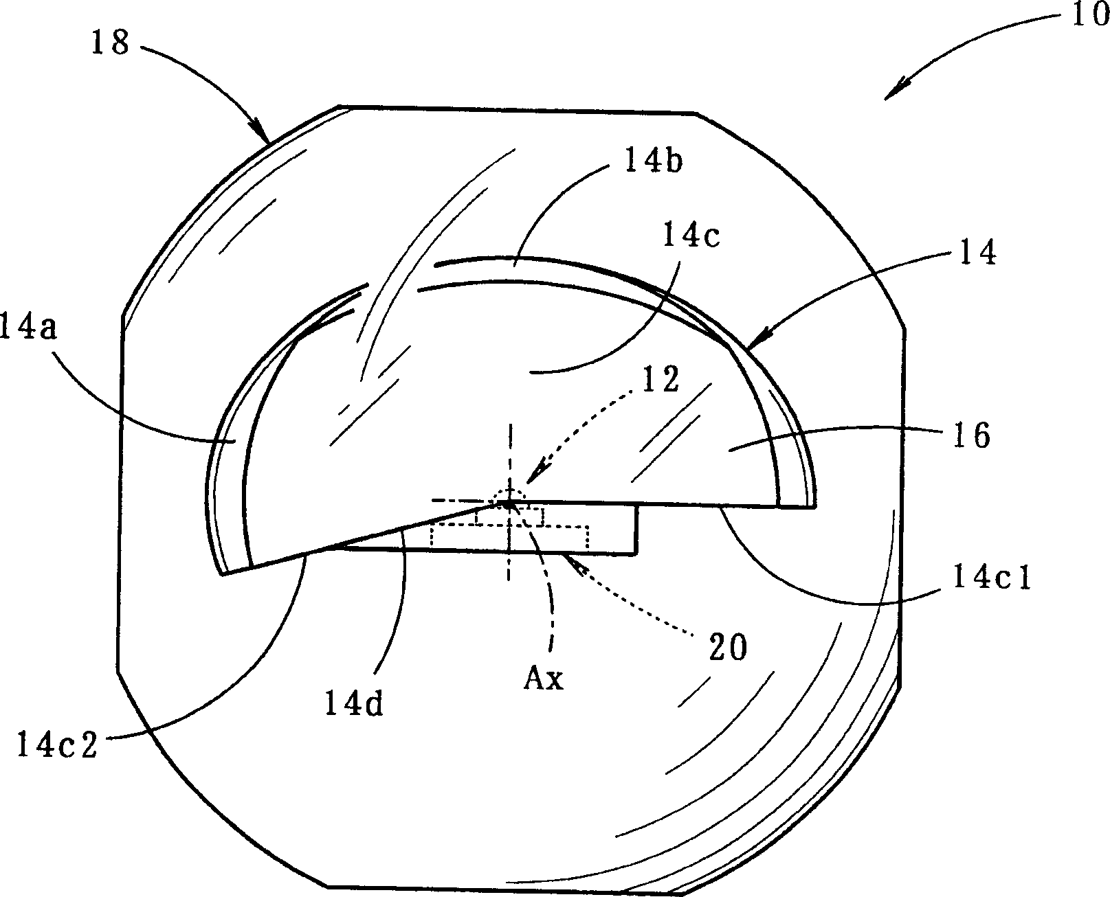
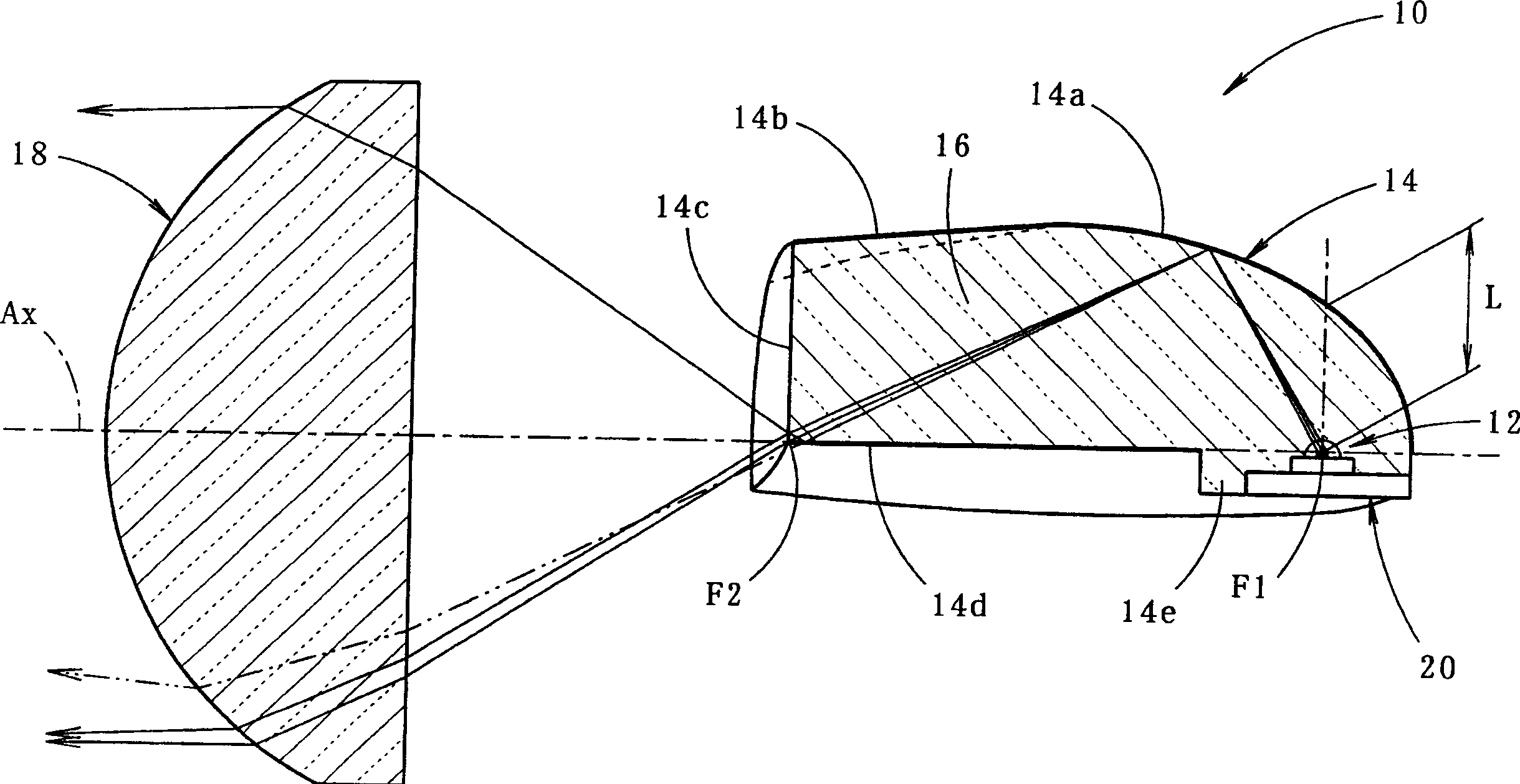
[0049] figure 2 To show a front view of a light source device 10, image 3 and 4 are side sectional views and plane sectional views thereof.

[0050] As shown in these figures, the light source device 10 includes an LED 12 (semicon...


PUM


Abstract

The invention provides a light source unit capable of downsizing a vehicle light fixture. An LED12 is disposed looking up the perpendicular direction on an optical axis Ax extending in the longitudinal direction of a vehicle. A reflector 14 is provided on its upper side which comprises a first reflecting surface 14a that condenses and reflects the light from the LED12 toward the front closer to the optical axis Ax. The reflector 14 is formed by treating the surface of a translucent block 16 which covers the LED12 for reflection surface, and a part of the surface is configured as the first reflecting surface 14a. Thus the reflector 14 is downsized compared to a conventional one. Using the LED12 as a light source suppresses the effect of heating and allows handling as a near point light source. So even if the reflector 14 is downsized, a proper reflection control is possible. By arranging the LED12 to be almost orthogonal to the optical axis Ax, the most of light outgoing from the LED12 can be used as the reflection light from the first reflecting surface 14a.

Description

technical field [0001] The invention relates to a light source device for a vehicle lamp. Background technique [0002] Conventionally, a so-called projection type lamp is known to be used as one of the types of lamps for vehicles such as headlights. [0003] The structure adopted by this type of projection vehicle lamp is as follows: through the reflector, the light emitted from the light source arranged on the optical axis is focused forward and reflected near the optical axis, and the projection lens arranged in front of the reflector is directed to the light source of the lamp. The reflected light is irradiated forward. [0004] Therefore, by adopting such a projection type vehicle lamp, it is possible to reduce the size of the lamp compared with a so-called parabolic vehicle lamp. [0005] However, in the conventional projection-type vehicle lamps, since the discharge light-emitting part of the discharge bulb or the filament of the halogen bulb is used as the light so...

Claims


Application Information

Patent Timeline
Patent Type & Authority Applications(China)
IPC IPC(8): F21S8/12F21S8/10F21V5/00F21V7/00F21V8/00F21V13/00F21W101/10F21Y101/02
CPCF21Y2101/02F21V2200/00F21S48/1329F21S48/1163F21S48/1241F21S48/1159F21V2008/00F21S48/125F21Y2115/10F21S41/155F21S41/24F21S41/25F21S41/322F21S41/16F21S41/151F21S41/148F21S41/33F21S41/141F21W2102/00F21Y2105/10
Inventor 石田裕之达川正士
Owner KOITO MFG CO LTD
Why Eureka
Try Eureka