Cleaning machine for tableware
A dishwashing machine and washing pump technology, applied in dishwashing machine/washing machine, dishwashing machine/rinsing washing machine parts, cleaning equipment, etc., can solve the problem of inability to achieve cleaning performance, damage to valve housing and valve body 14, etc. question
- Summary
- Abstract
- Description
- Claims
- Application Information
AI Technical Summary
Problems solved by technology
Method used
Image
Examples
Embodiment 1
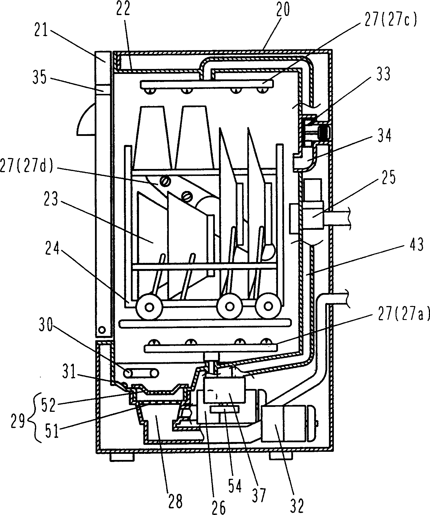
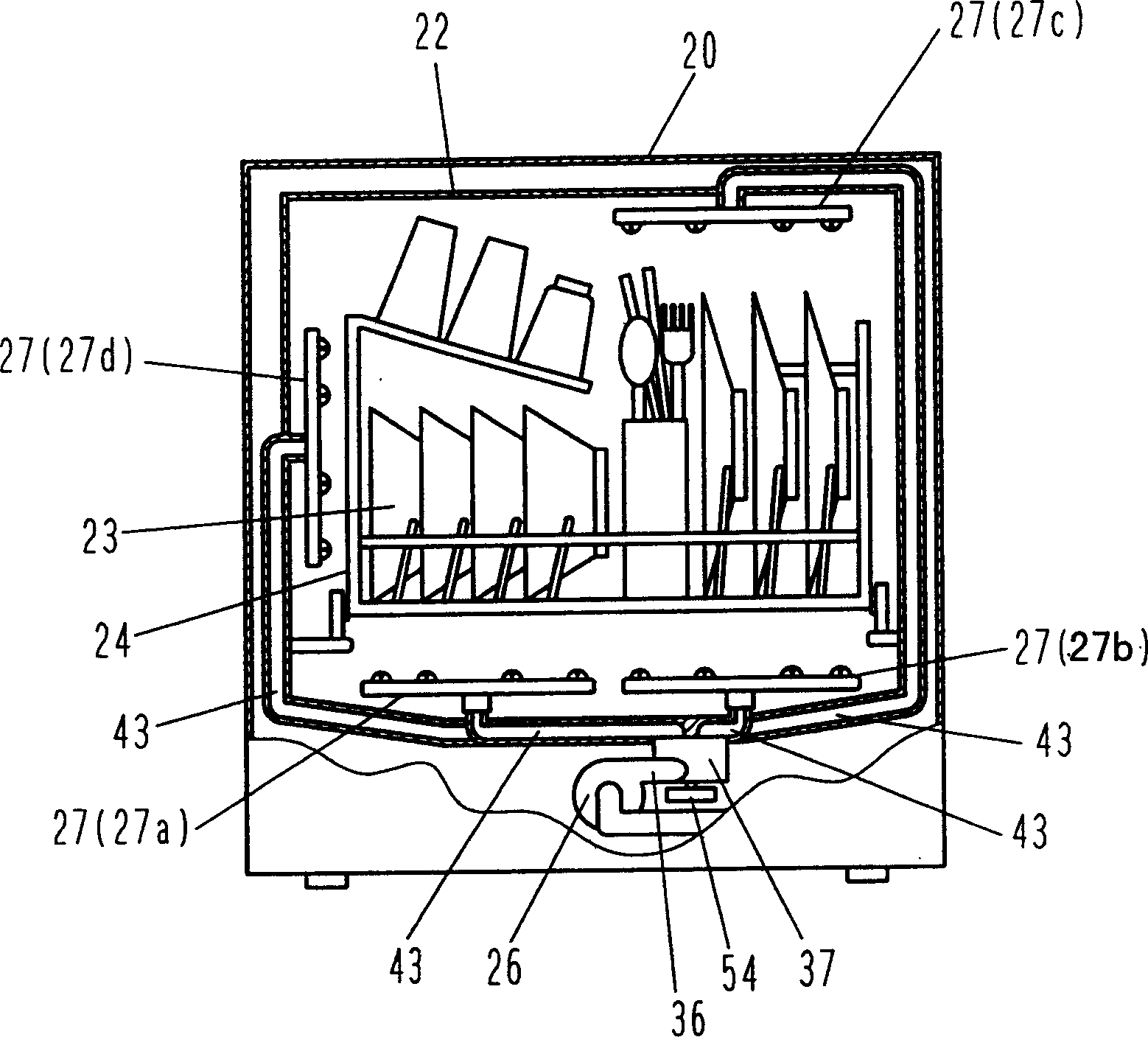
[0091] Such as Figure 1 to Figure 5 As shown in , the main body 20 of the dish washer is provided with a cleaning tank 22 that can be opened and closed through a door 21 . The water inlet valve 25 supplies washing water into the washing tank 22 . Washing pump 26 pressurizes the washing water, and supplies it to washing device (washing nozzle) 27 provided with a plurality of spray holes, and this washing device 27 sprays washing water. In the cleaning device 27, nozzles 27a, 27b sprayed from the bottom of the tableware basket 24, nozzles 27c sprayed from the upper right, nozzles 27d sprayed from the left side, etc. are provided at four positions. Rotating nozzle with shaft rotation.
[0092] The bottom of cleaning tank 22 is provided with the drain port 28 that communicates with the suction side of cleaning pump 26, and this drain port 28 is provided with the leftovers filter screen 29 that is used to collect leftovers and the heating device 30 that heats usefulness, and is ...
Embodiment 2
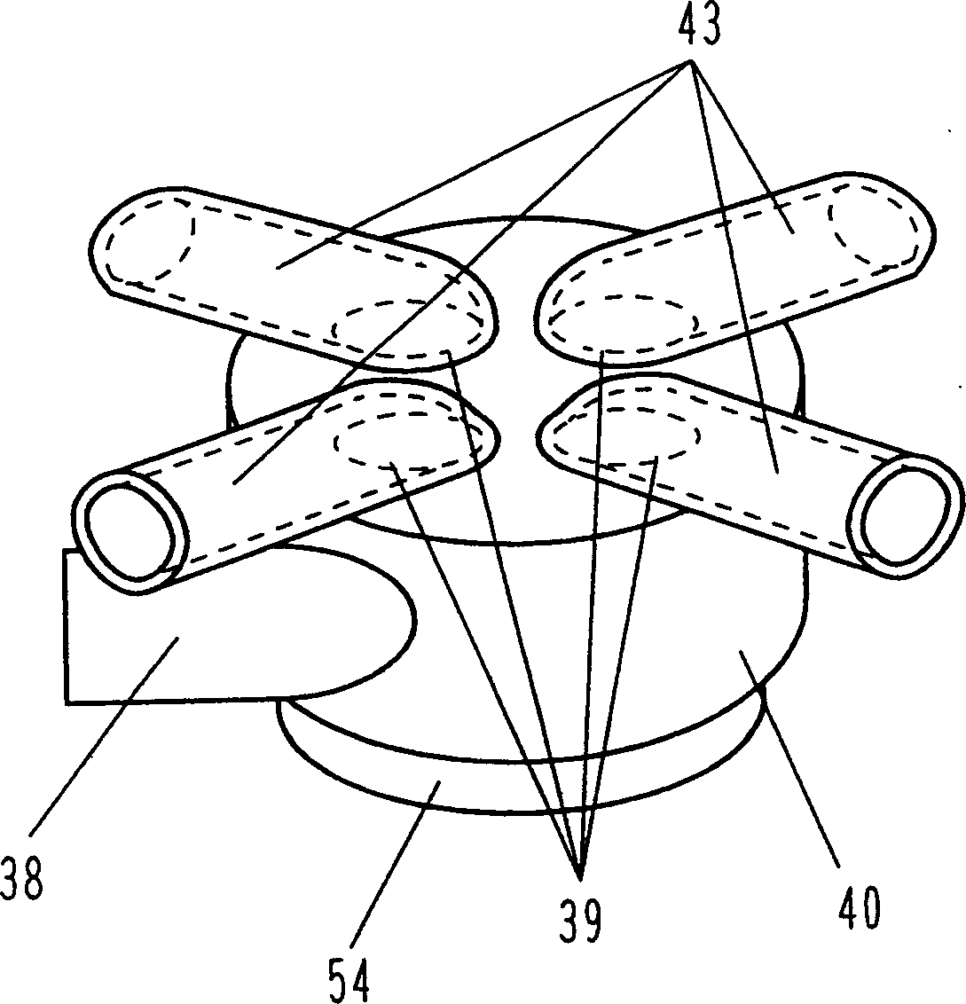
[0141] The structure of the water dividing device 37 in the present embodiment is as Figure 14 , Figure 15 As shown, it is composed of a valve casing 40 provided with an inlet 38 and four outlets 39 and a movable valve body 41 as in Embodiment 1. The valve body 41 is provided with an opening 42 through which washing water passes. However, the drive motor 54 for driving the valve body 41 is omitted. As an alternative component, a set of upper engaging parts 44 that rotate the valve body 41 at a predetermined angle when the valve body 41 rises and a set of upper engaging parts 44 that rotate the valve body 41 when the valve body 41 descends are respectively provided on the valve housing 40 side and the valve body 41 side. A set of lower engaging members 45 at a prescribed angle.
[0142] Such as Figure 14 As shown in , the valve casing 40 is slightly cylindrical, and its axial direction is roughly arranged in the vertical direction. The inflow port 38 for the washing wate...
Embodiment 3
[0174] Figure 26 ~ Figure 28 The case where the opposing surface of the outflow port 39 and the valve body 41 is not a planar shape is shown in .
[0175] Figure 26 Shown in is the case where the opposing surfaces of the outflow port 39 and the valve body 41 are conical. As shown in the figure, the opposite surface is somewhat inclined from the horizontal, so that when the valve body 41 is separated from the outlet 39, the possibility of stuck foreign matter 49 remaining on the valve body 41 can be reduced, thereby providing a method for removing foreign matter 49. The higher water dividing device 37 of function. In addition, the direction of the rotation axis is inclined from the horizontal direction regardless of the direction in which it is set, which can produce a good effect.
[0176]In addition, even in the state where the outlet 39 is in contact with the valve body 41, the valve body 41 can also rotate, and the channel switching of the washing water is independent ...
PUM
 Abstract
Description
Claims
Application Information
 - R&D
- Intellectual Property
- Life Sciences
- Materials
- Tech Scout
- Unparalleled Data Quality
- Higher Quality Content
- 60% Fewer Hallucinations
Browse by: Latest US Patents, China's latest patents, Technical Efficacy Thesaurus, Application Domain, Technology Topic, Popular Technical Reports.
© 2025 PatSnap. All rights reserved.Legal|Privacy policy|Modern Slavery Act Transparency Statement|Sitemap|About US| Contact US: help@patsnap.com


