
Communication appts. and installing structure, mfg. method and communication method

A communication device, transmitter technology, applied in the direction of the antenna support/installation device, the activation of the identification card or credit card with the code, the antenna, etc.

Inactive Publication Date: 2003-12-24
HANEX CO LTD
View PDF5 Cites 17 Cited by
  • Summary
  • Abstract
  • Description
  • Claims
  • Application Information

AI Technical Summary

Problems solved by technology

However, using the previous method, since it is necessary to insert the sheet-shaped magnetic material 8 into the antenna coil 2a, it is necessary to manufacture the standard product in a different way.

Method used


Image

  • Communication appts. and installing structure, mfg. method and communication method
  • Communication appts. and installing structure, mfg. method and communication method
  • Communication appts. and installing structure, mfg. method and communication method

Examples


Embodiment Construction

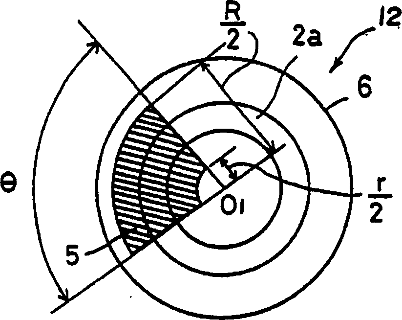
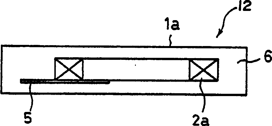
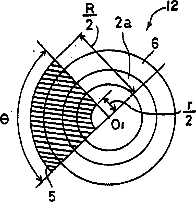
[0107] Embodiments of the present invention relating to a communication device, a mounting structure of the communication device, a method of manufacturing the communication device, and a method of performing communication using the communication device will be described in detail below with reference to the accompanying drawings. As an example of the structure of the proposed communication device 12, reference is made below to FIGS. Figure 4The configuration of the RFID tag 1a having the flat concentric disk antenna coil 2a will be described. The RFID tag 1a preferably applied to this embodiment relates to both the electromagnetic field coupling type and the electromagnetic field induction type, although the following description is specifically directed to the latter type.

[0108] The RFID tag 1a shown in FIGS. 1 to 3 is an example of a communication device 12 that communicates with electromagnetic waves using an antenna coil 2a; the RFID tag 1a has a flat concentric disk-s...


PUM


Abstract

This invention aims to provide a communication device, installation structure for the communication device, a method of manufacturing the communication device, and a method of communication with the communication device in which the communication device is able to exceedingly restain a conductive material from attenuating magnetic flux and to expand communication distance even when the communication device is attached to a conductive member e.g., metal, in a closely contacting manner. An RFID tag serving as a communication device is characterized in that an amorphous magnetic sheet extends from a magnetic flux generation portion of a concentric display antenna coil of the RFID tag toward the outside of the antenna coil.

Description

technical field [0001] The present invention relates to a communication device using an antenna coil for electromagnetic wave communication, a mounting structure of the communication device, a method of manufacturing the communication device and a communication method using the communication device. [0002] Japanese Patent Application No.2001-3403 filed on January 11, 2001, Japanese Patent Application No.2001-124010 filed on April 23, 2001, and Japanese Patent Application No.2001-139044 filed on May 9, 2001 It is hereby incorporated by reference in its entirety for purposes of claiming foreign priority. Background technique [0003] RFID (Radio Frequency-IDentificationTAG) tags with antenna coils and control devices such as IC circuits or data carriers (submachines) such as non-contact IC cards are widely used in various occasions as A communication device that communicates by electromagnetic waves, wherein the communication device communicates with a read / write device (re...

Claims


Application Information

Patent Timeline
Patent Type & Authority Applications(China)
IPC IPC(8): G06K19/07G06K19/077H01Q1/22H01Q7/00H01Q7/08
CPCH01Q7/00H01Q1/22H01Q1/2225G06K19/0723H01Q7/08G06K19/07749G06K19/07771H01Q7/06
Inventor 仙波不二夫兵头仲麻吕坂根铁志藤井润内山知树木田茂
Owner HANEX CO LTD
Learn More