Water drop proof tap

A faucet, anti-drip technology, applied in the direction of lift valve, valve details, engine components, etc., can solve the problems of increasing assembly process, lack of flexibility, increasing manufacturing cost, etc., reducing accessories and materials, reducing manufacturing accuracy, and reducing manufacturing costs. Effect

Inactive Publication Date: 2004-01-07
蔡松城
View PDF1 Cites 9 Cited by
  • Summary
  • Abstract
  • Description
  • Claims
  • Application Information

AI Technical Summary

Problems solved by technology

[0002] The application for invention with the application number 00130747.9 discloses a rotary opening and closing floating spool stop valve, which consists of a valve body, spool, valve stem, bonnet, seal and valve stem control device, although it solves the water hammer phenomenon , it is easy to control the water output, but the handle cover is an overall cylindrical shape, has many consumables, lacks elasticity, is difficult to disassemble, the socket area with the handle is too large, and the manufacturing precision is high; moreover, the valve stem control device must be fixed through the fixing ring. Limits, many accessories, many threads, not only increase the assembly process, increase the manufacturing cost, but also reduce the stability of product quality
In addition, none of the existing faucets can solve the problem of anti-dripping, especially the problem of artificial dripping.

Method used


Image

  • Water drop proof tap
  • Water drop proof tap
  • Water drop proof tap

Examples


Embodiment Construction

[0007] Below in conjunction with accompanying drawing and embodiment the present invention will be further described:

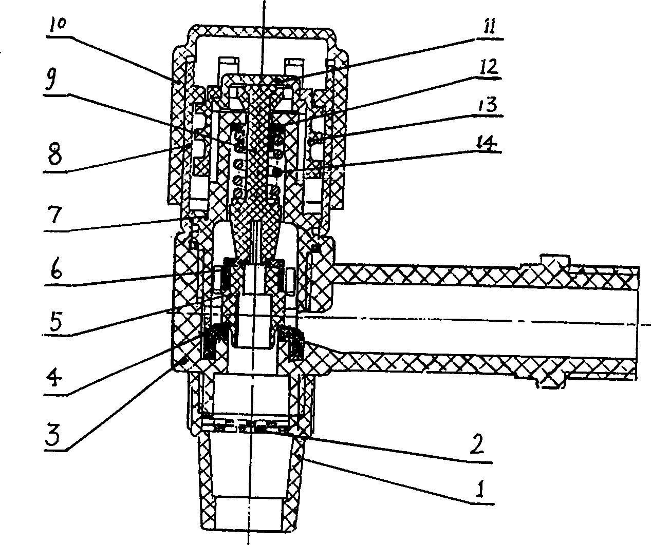
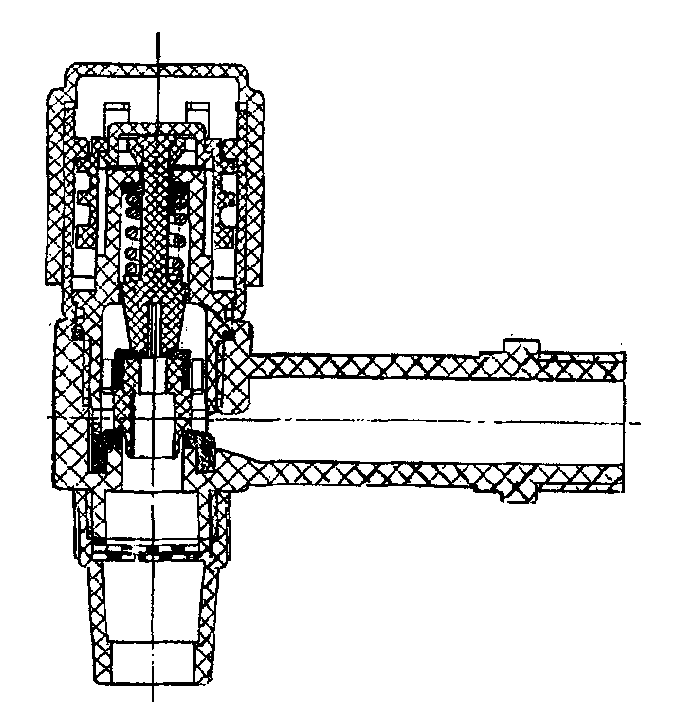
[0008] figure 1 It is a longitudinal sectional structure diagram of the present invention.

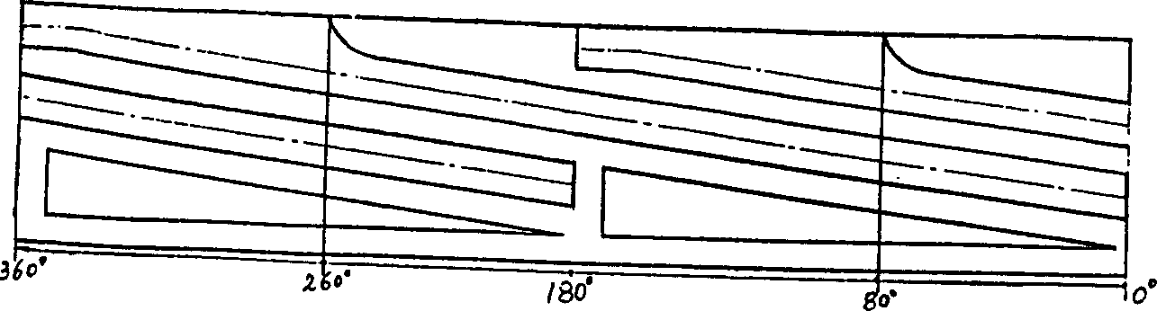
[0009] figure 2 It is the expanded view of the outer wall of the pull cover.

[0010] In the figure, 1. Faucet 2. Filter net 3. Valve body 4. Valve body sealing ring 5. Valve core 6. Valve core sealing ring 7. Valve cap 8. Handle seat 9. Valve stem 10. Handle 11. Buckle cover 12. Stem sealing ring 13. Pull cover 14. Spring

[0011] figure 1 Shown is a rotary opening and closing floating spool valve, which consists of a three-way valve body (3), a floating spool (5), a valve stem (9), a bonnet (7), a sealing ring and a valve stem control device Composition; the upper end of the valve stem (9) passes through the valve stem sealing ring (12), the valve cap (7) and the pull cover (13) and then thermally sinters, and the snap-in buckle cover (11) connects it with the...


PUM


Abstract

The invention relates to the valve, especially valves with floating valve core in type of open and close by rotation. The valve is composed of the triple valve body, the floating valve core, the valve rod, the valve cap, the seal ring and the unit for controlling the valve rod. By taking full advantage of elasticity characteristics of the plastics, an erect claw is utilized to replace a cylinder.The circular bead is utilized to limit and lock the erect claw so as to reduce manufacturing accuracy needed as well as number of parts, material and cost. Since the steep fall structure of screw thread and the spring are used, the valve can return to closed position automatically when water quantity is low so as to solve the drip issue caused by not closing water faucet tightly or mild wear of seal ring. The stability of quality of the product is also raised.

Description

[technical field] [0001] The present invention relates to a valve, especially a valve stem control device for a floating valve core valve. [Background technique] [0002] The invention application with the application number 00130747.9 announced a rotary opening and closing floating spool stop valve, which is composed of a valve body, spool, valve stem, bonnet, seal and valve stem control device, although it solves the water hammer phenomenon , it is easy to control the water output, but the handle cover is an overall cylindrical shape, has many consumables, lacks elasticity, is difficult to disassemble, the socket area with the handle is too large, and the manufacturing precision is high; moreover, the valve stem control device must be fixed through the fixing ring. Limits, many accessories, and many threads not only increase the assembly process, increase manufacturing costs, but also reduce the stability of product quality. In addition, none of the existing faucets can s...

Claims


Application Information

Patent Timeline
Patent Type & Authority Applications(China)
IPC IPC(8): F16K1/00F16K31/56
Inventor 蔡松城
Owner 蔡松城
Why Eureka
Try Eureka