Tissue supporting device for medical treatment

A technology of living tissue and supporting device, applied in the fields of application, medical science, surgery, etc., can solve the problems of taking a lot of time, low precision, and inability to use

Inactive Publication Date: 2004-01-07
JMS CO LTD
View PDF0 Cites 5 Cited by
  • Summary
  • Abstract
  • Description
  • Claims
  • Application Information

AI Technical Summary

Problems solved by technology

However, in order to measure the thickness of the valve, if it takes a lot of time and effort, it is not suitable for t

Method used


Image

  • Tissue supporting device for medical treatment
  • Tissue supporting device for medical treatment
  • Tissue supporting device for medical treatment

Examples


Embodiment 1

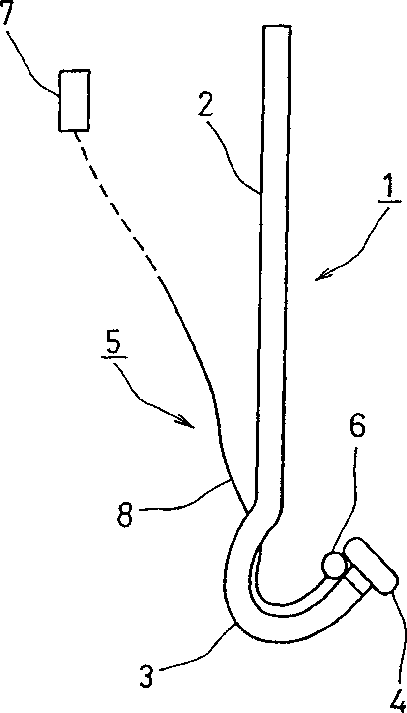
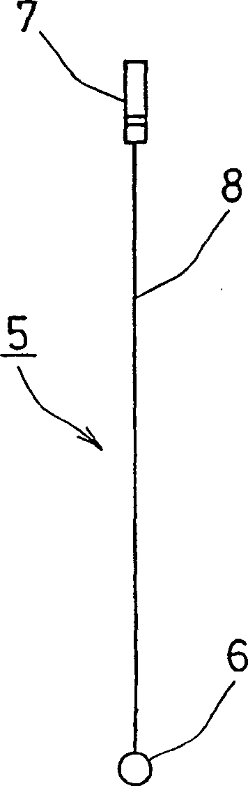
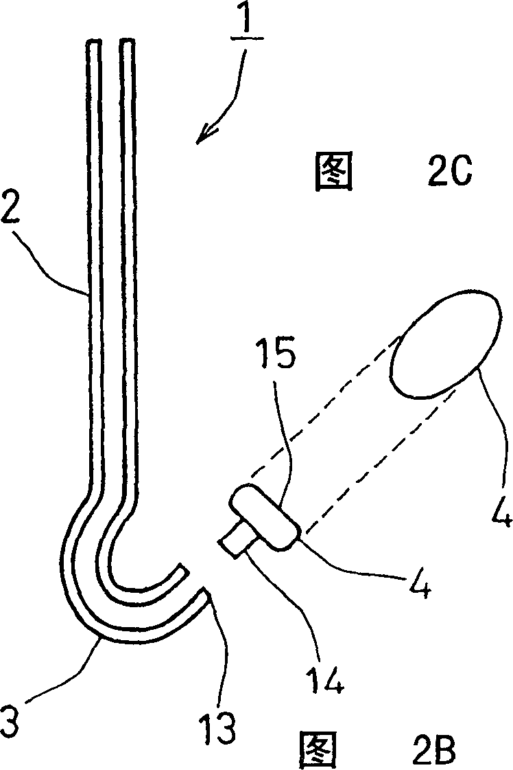
[0110] for Figure 17 The living tissue support device of the form shown represents an example of the dimensions of the various parts. The length L1 of the rod part 2 is 150mm, and the length L2 of the hook part 3 is 60mm when it is extended. Both the rod part 2 and the hook part 3 are made of φ3.5×φ5.0 stainless steel (SUS 304, SUS 316) hollow tubes . The curvature of each part of the hook part 3: the connection part 9 connected to the rod part 2 is R30, the first middle part 10 is R25, the second middle part 11 is R8, and the front end side curved part 12 is R15. An angle α1 formed by a tangent to the distal end side curved portion 12 and a straight line drawn parallel to the axis of the hook distal end portion 13 is 45°.

[0111] The support platform 4 embedded in the front end portion 13 of the hook is set in a prismatic shape as shown in FIG. 18 or a pillow shape as shown in FIG. 19 .

[0112] Figure 18A It is the figure which looked at prismatic support stand 4h fro...

Embodiment 2

[0115] A support device of the shape shown in FIG. 11 is made. The shaft portion 20 has a length of 250 mm, an outer diameter of 5.0 mm, and an inner diameter of 3.0 mm. As the light projection device, the existing catheter fiber is adopted, and the diameter of the optical fiber 22 is 2.3mm. The prism of the support stand 21 is detachable and replaceable, and is an oblong flat surface with a long diameter of 20 mm and a short diameter of 10 mm, and a height of 14 mm. The optical fiber insertion hole 25 has a diameter of 3.1 mm and a depth of 8.0 mm.

[0116] The above-mentioned embodiment is an example of the dimensions of each part, and of course, each illustrated dimension can be appropriately adjusted.


PUM

PropertyMeasurementUnit
Lengthaaaaaaaaaa
Lengthaaaaaaaaaa
Outer diameteraaaaaaaaaa

Abstract

The invention provides a biomedical tissue support device for supporting, during valve repair, an unhealthy part to be excised, and performing the surgical procedure swiftly and accurately. The device includes a substantially straight rod portion (2), a curved hook portion (3) that is linked to a front end of the rod portion, and a support prop (4) connected to the hook portion's front end. The support prop has a shape that is more expanded than a connection portion to the front end of the hook portion.

Description

technical field [0001] The present invention relates to a living tissue supporting device for medical treatment used for assisting in cutting a part of hypertrophic tissue with a high-speed rotary electric file during valvuloplasty for repairing a heart valve disease. Background technique [0002] Among the treatment methods for heart valve diseases, artificial valves are used to replace the diseased heart valves of patients with valvular disease, and valvuloplasty is used to repair and form the diseased heart valves. The former valve replacement has been continuously improved with the development of artificial valves and has been used clinically. Recently, although the surgical performance of valve replacement is stable, the artificial valves currently used are not ideal, and considering the complications caused by the artificial valve itself and the anticoagulant therapy that must be performed after the operation, it is difficult to say that it is a perfect treatment metho...

Claims


Application Information

Patent Timeline
IPC IPC(8): A61B17/00A61B17/02A61B17/32
CPCA61B2017/00783A61B2017/320052A61B17/320016A61B2017/0237
Inventor 北村信夫上村晋一
Owner JMS CO LTD
Why Eureka
Try Eureka