Medical device for temporarily treating flail chest injury

Inactive Publication Date: 2008-01-31
SMITH GEORGE K
View PDF9 Cites 11 Cited by
  • Summary
  • Abstract
  • Description
  • Claims
  • Application Information

AI Technical Summary

Benefits of technology

[0009] Still another object of the present invention is to provide a medical device for a flail chest injury that is relatively inexpen

Problems solved by technology

However, a flail segment will not resist the decreased pressure and will appear to push in while the rest of the rib cage expands.
The constant motion of the ribs in the fl

Method used


Image

  • Medical device for temporarily treating flail chest injury
  • Medical device for temporarily treating flail chest injury
  • Medical device for temporarily treating flail chest injury

Examples


Embodiment Construction

, particularly, when such description is taken in conjunction with the attached drawing figures and with the appended claims.

BRIEF DESCRIPTION OF THE DRAWINGS

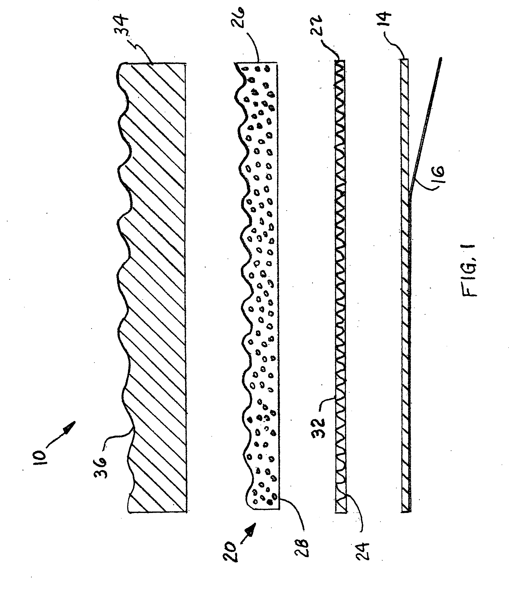
[0012]FIG. 1 is an exploded side view of a medical device for a flail chest injury according to the present invention; and

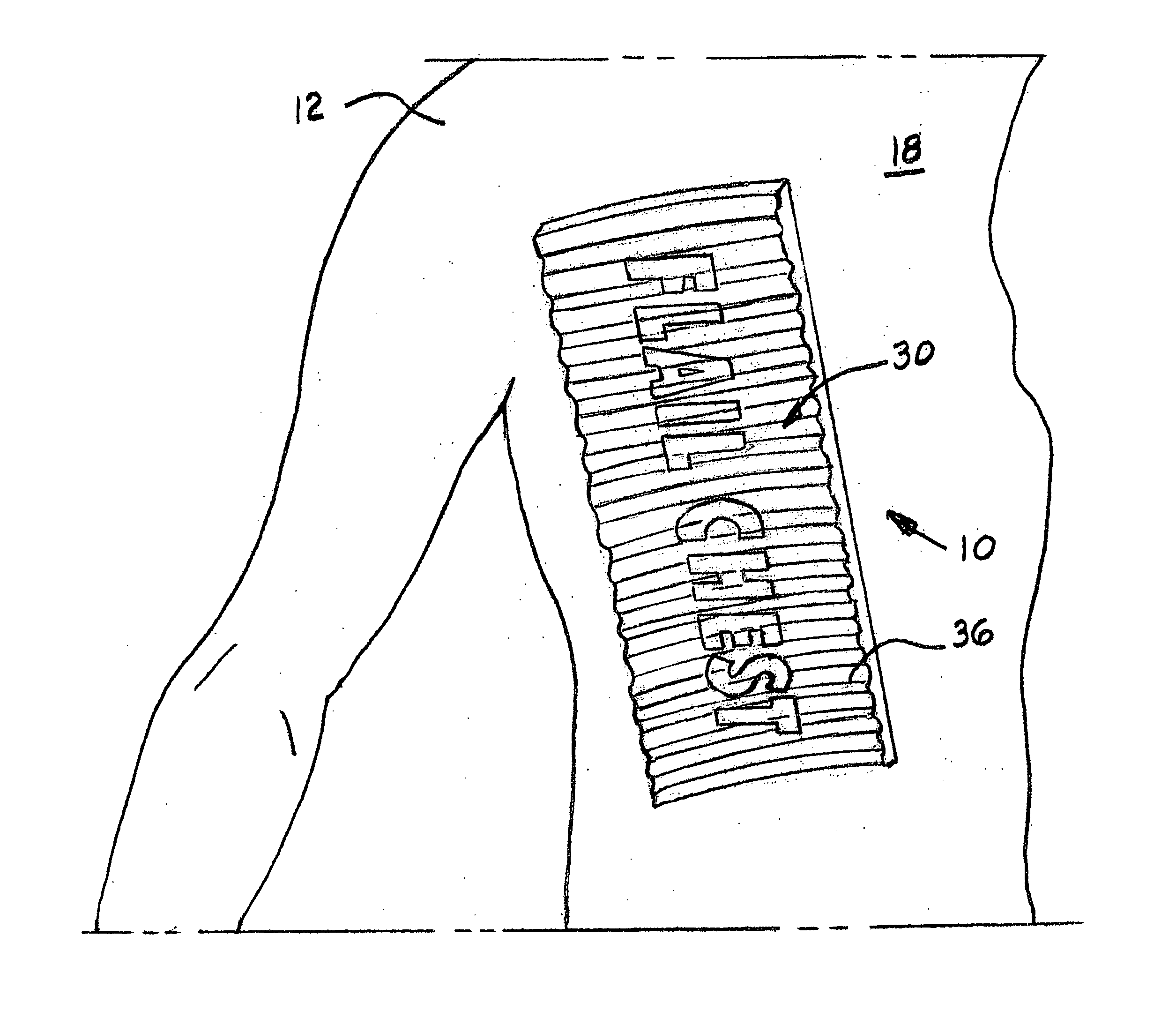
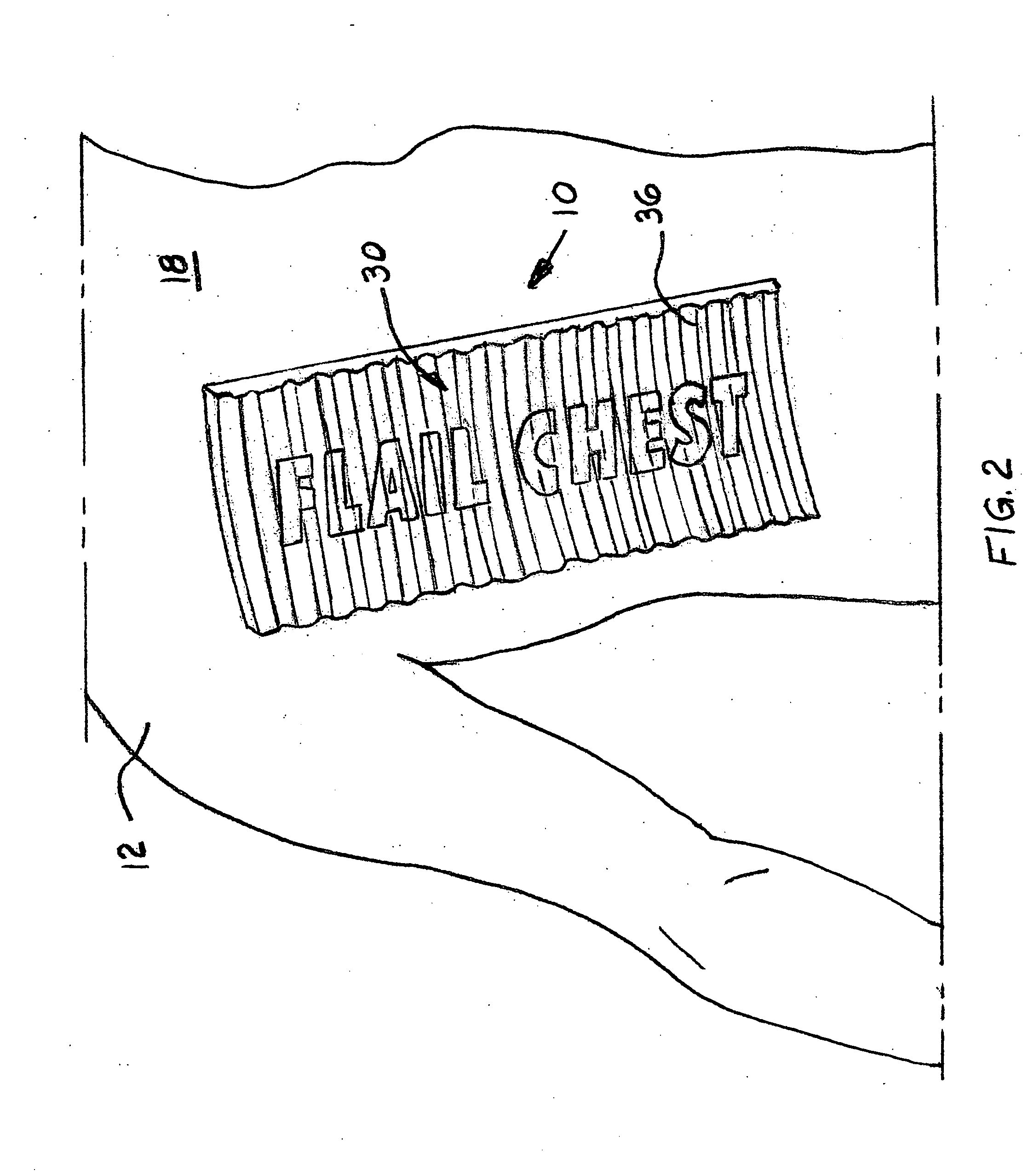
[0013]FIG. 2 is a perspective view of the medical device, illustrated in FIG. 1, attached to a person having a flail chest injury.

DETAILED DESCRIPTION OF A PRESENTLY PREFERRED AND VARIOUS ALTERNATIVE EMBODIMENTS OF THE INVENTION

[0014] Prior to proceeding to the more detailed description of the present invention it should be noted that, for the sake of clarity and understanding, identical components which have identical functions have been identified with identical reference numerals throughout the several views illustrated in the drawing figures.

[0015] Reference is now made, more particularly, to drawing FIGS. 1 and 2. Illustrated therein is a medical device, generally designated 10, for temporarily trea...


PUM


Abstract

A medical device for temporarily treating an individual having a flail chest injury prior to and during transport of the individual for further medical treatment. The medical device includes a flexible member engageable with a flail segment of an individual that provides skin traction to the flail segment of the individual for stabilizing paradoxical motion of such flail segment during respiration. There is an adhesive layer disposed on the flexible member for temporarily adhering it to the flail segment of the individual.

Description

CROSS REFERENCE TO RELATED APPLICATION [0001] This application is closely related to and claims priority from U.S. Provisional Patent Application Ser. No. 60 / 833,050 filed on Jul. 25, 2006.FIELD OF THE INVENTION [0002] The present invention relates, in general, to medical devices used to treat various chest related injuries and, more particularly, the invention relates to a medical device for temporarily treating an individual having a flail chest injury prior to and during transport of such individual for further medical treatment. BACKGROUND OF THE INVENTION [0003] The following information on flail chest injuries is from Wikipedia®, a registered trademark of the Wikimedia Foundation, Inc. A flail chest injury occurs when a segment of the thoracic wall breaks under extreme stress and becomes detached from the rest of the chest wall. This typically occurs when three or more ribs are fractured in two or more places, allowing that segment of the thoracic wall to displace and move ind...

Claims


Application Information

Patent Timeline
IPC IPC(8): A61H31/00
CPCA61F13/143
Inventor SMITH, GEORGE K.
Owner SMITH GEORGE K
Why Eureka
Try Eureka