

Pump
A technology of pump cavity and outlet flow channel, applied in the direction of pump, pump control, pump components, etc., can solve the problems of pressure drop, operation failure, inability to achieve miniaturization, high efficiency, etc.
- Summary
- Abstract
- Description
- Claims
- Application Information
AI Technical Summary
Problems solved by technology
Method used
Image

Examples
Embodiment Construction
[0035] Embodiments of the pump according to the present invention will be described in detail below with reference to the accompanying drawings.
[0036] (1) The first embodiment
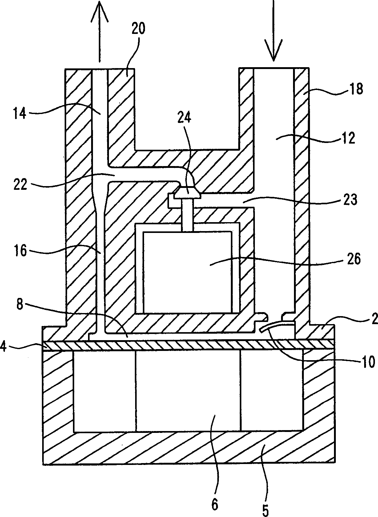
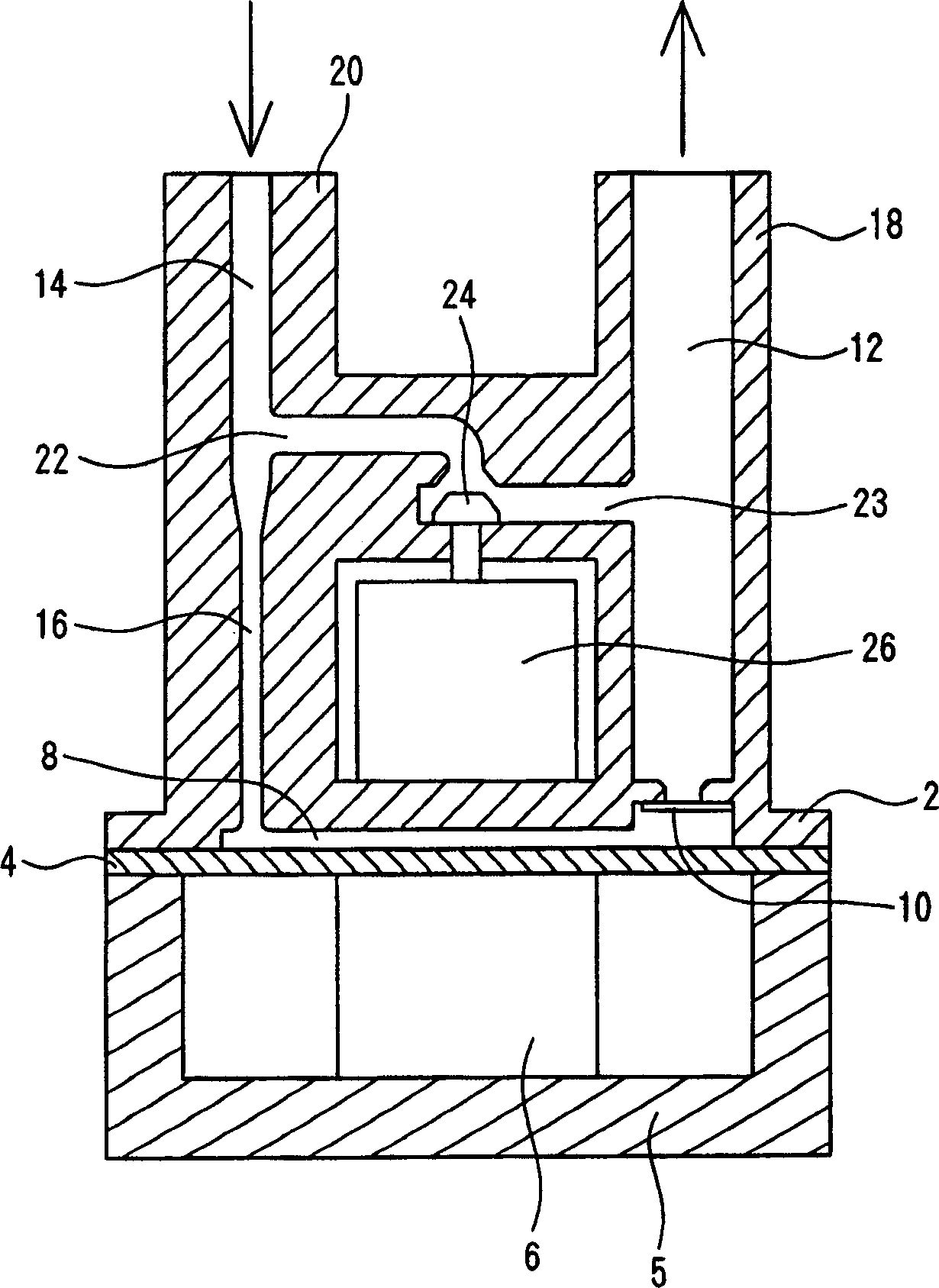
[0037] figure 1 is a longitudinal sectional view of the pump according to the first embodiment of the present invention. exist figure 1 Among them, a circular diaphragm 4 is set at the bottom of the cylindrical housing 2 . The diaphragm 4 is free to deform elastically, while its edges are rigidly supported by the housing 2 . Underneath the diaphragm 4 , a piezoelectric member 6 that expands and contracts in the vertical direction in the figure is installed in its own housing 5 as an actuator for moving the diaphragm 4 .
[0038] The elongated space between the diaphragm 4 and the top wall of the housing 2 forms a pump chamber 8 . An inlet flow channel 12 and an outlet flow channel 14 lead to the pump chamber 8 , wherein a check valve 10 serving as a fluid resistance is installed in the inlet fl...
PUM
 Abstract
Description
Claims
Application Information