Surface wave apparatus

A surface wave device and surface wave technology, applied in impedance networks, electrical components, etc., can solve the problems of cracks or fragments in piezoelectric substrates, increase costs, and increase the size of surface wave devices.

Inactive Publication Date: 2004-01-21
MURATA MFG CO LTD
View PDF4 Cites 0 Cited by
  • Summary
  • Abstract
  • Description
  • Claims
  • Application Information

AI Technical Summary

Problems solved by technology

Therefore, the size of the surface wave device has to be increased
In addition, additional materials such as sound-absorbing materials are also required, and processes such as applying sound-absorbing materials must be carried out
Therefore, there is a problem of lowering productivity and raising costs
[0016] On the other hand, in the structure in which grooves are formed on the piezoelectric substrate between adjacent surface wave elements as in Patent Document 4 above, the size of the surface wave device has to be increased because the grooves must be formed.
In addition, when the groove is formed, cracks or chips can also be generated on the piezoelectric substrate
In addition, since the process of forming the groove must be implemented, the production process is cumbersome and the yield rate is reduced.

Method used


Image

  • Surface wave apparatus
  • Surface wave apparatus
  • Surface wave apparatus

Examples


Embodiment 2

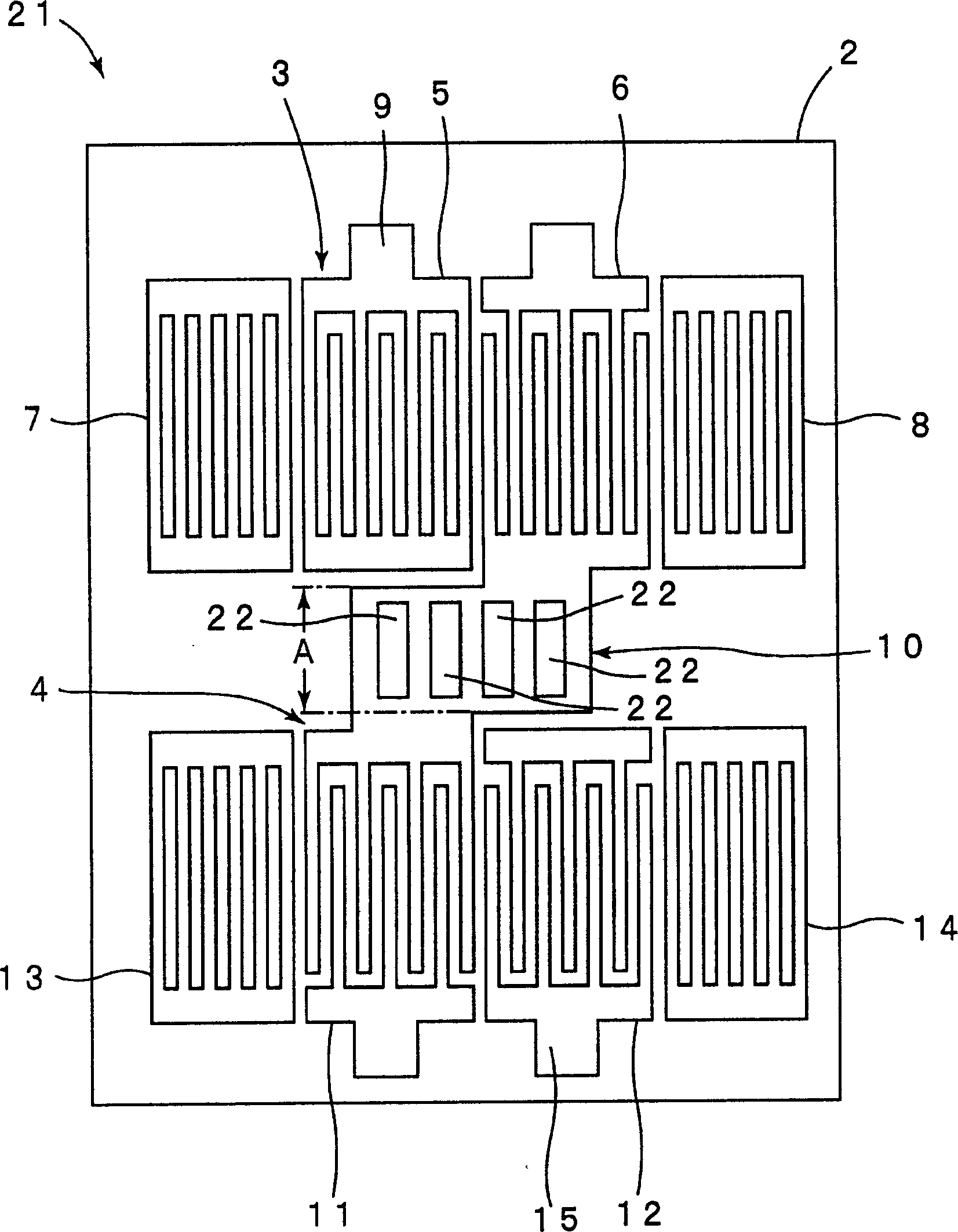
[0053] In the surface wave device 21 of the second embodiment, a plurality of elongated slits 22 serving as through-holes are formed in the inter-segment connection portion 10 . A free surface section is formed in this gap 22 . In this embodiment, the longitudinal direction of the slit 22 is a direction perpendicular to the surface wave propagation direction of the first and second surface wave filter elements 3 and 4 .

[0054] Thus, in the present invention, the slit 22 having the longitudinal direction may be provided as the through-hole constituting the free surface portion.

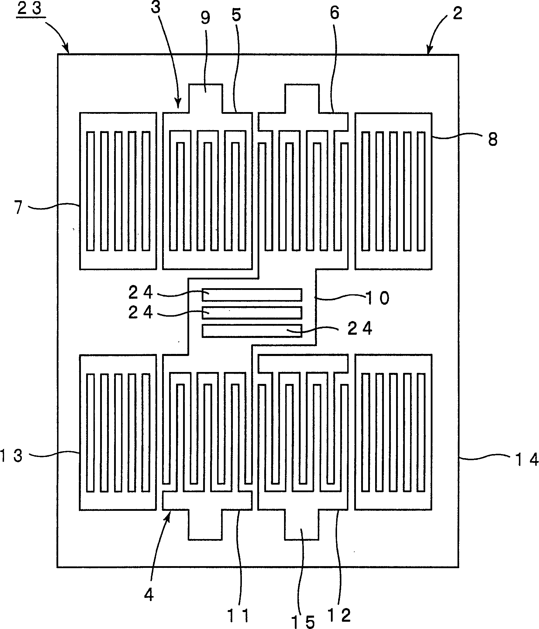
[0055] image 3 It is a plan view showing a surface wave device according to a modified example of the second embodiment. exist figure 2 In the shown surface wave device 21, a plurality of slits 21 are formed to extend in a direction perpendicular to the surface wave propagation direction of the surface wave filter elements 3, 4, but as image 3 Like the surface wave device 23 shown, the plurali...


PUM


Abstract

A surface acoustic wave device has first and second surface acoustic wave filter elements which are arranged on a surface acoustic wave substrate so as to define a filter device having a two-stage configuration. A free surface portion is provided by forming a perforation in an inter-stage connecting portion connecting the first and second surface acoustic wave filter elements.

Description

technical field [0001] The present invention relates to a surface wave device used, for example, as a resonator and a bandpass filter, and more specifically, to a surface wave device having a multi-stage structure. Background technique [0002] Conventionally, there have been disclosed various surface wave devices in which the attenuation amount is increased by connecting a plurality of surface wave filter elements vertically. Figure 9 An example of such a surface acoustic wave device is shown in plan view. [0003] The surface wave device 101 has a piezoelectric substrate 102 . On the piezoelectric substrate 102, a vertically coupled first surface wave filter element 103 and a vertically coupled second surface wave filter element 104 are provided. The surface wave filter elements 103 and 104 are electrically connected by an inter-segment connection portion 105 . The interdigital transducers, reflectors, and inter-segment connection portions 105 constituting the surface w...

Claims


Application Information

Patent Timeline
Patent Type & Authority Applications(China)
IPC IPC(8): H03H9/25H03H9/00H03H9/02H03H9/145H03H9/64
CPCH03H9/02905H03H9/6459H03H9/02889H03H9/0028H03H9/64
Inventor 玉崎大辅中尾武志米田年麿
Owner MURATA MFG CO LTD
Why Eureka
Try Eureka