
Folding direction-finding communication line antenna apparatus

An antenna device and communication line technology, applied in the fields of communication antennas and direction-finding antennas, can solve the problems of unfavorable transportation and storage, increased shrinkage volume, poor operability, etc., and achieve convenient batch processing and production, small shrinkage volume, and mobility Good results

Inactive Publication Date: 2004-01-28
NO 54 INST OF CHINA ELECTRONICS SCI & TECH GRP
View PDF0 Cites 16 Cited by
  • Summary
  • Abstract
  • Description
  • Claims
  • Application Information

AI Technical Summary

Problems solved by technology

[0003] The existing domestic vehicle-mounted antennas, such as the direction-finding antennas and communication antennas produced by the former Ministry of Electronics 54, have poor mobility and need to be fixed with screws every time they are erected or withdrawn, which is cumbersome to use
[0004] In similar foreign products, such as the direction-finding antenna produced by the American WJ company, the upper and lower vibrators cannot be folded when shrinking, so the shrinkage volume increases significantly, and there is no positioning device, which is not conducive to transportation and storage
[0005] In addition, whether it is a domestic or foreign antenna, it needs some accessories when it is stored. It needs to be reinstalled every time it is erected, and some need special tools. Therefore, the operability is poor.

Method used


Image

  • Folding direction-finding communication line antenna apparatus
  • Folding direction-finding communication line antenna apparatus
  • Folding direction-finding communication line antenna apparatus

Examples


Embodiment Construction

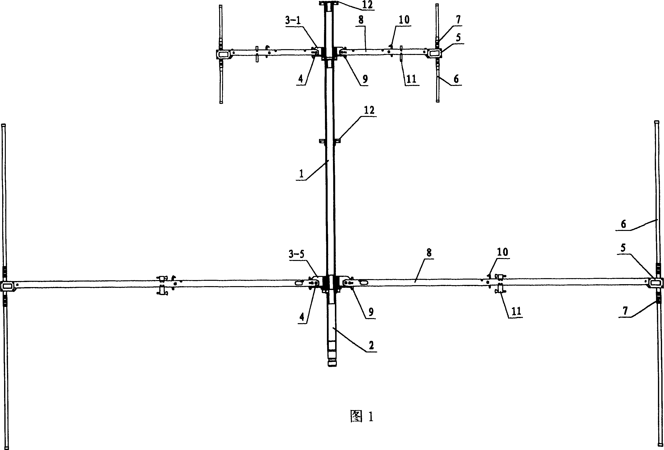
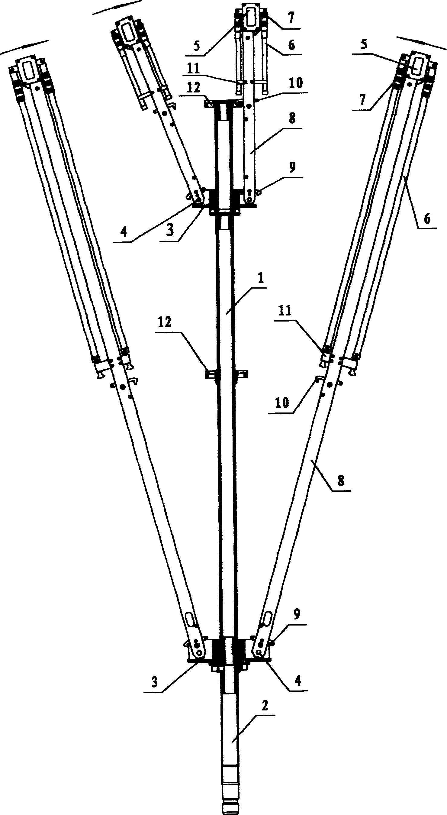
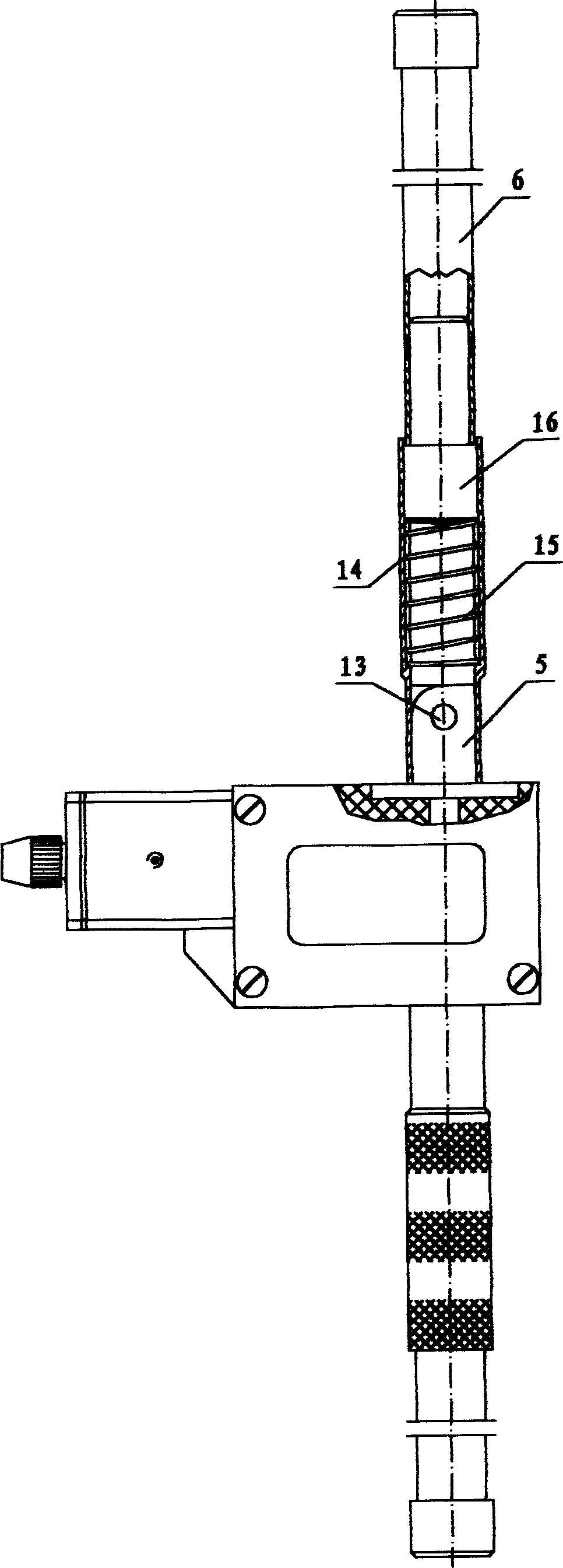
[0018] Refer to Figure 1 to image 3 , the present invention consists of a central rod 1, a connecting rod 2, 1 to 5 bases 3-1 to 3-5, a shaft rod 4, and 1 to 5 layers of folding unit antenna arrays, and each layer of folding unit antenna arrays consists of 2 to 10 Each folded element line antenna is composed of a feed box 5, a folded vibrator 6, a sleeve 7, a folded cross arm 8, positioning pieces 9, 10, 11, and a fixing piece 12. In the present invention, 1 to 5 bases 3-1 to 3-5 are processed into a disc base structure with aluminum plate or steel plate material, and 2 to 10 U-shaped groove structures and hook groove structures are processed on the circumference, and are fixed in sequence from top to bottom. On the center pole 1, its function is to movably fix and support each folded element line antenna array of each layer. The lower end of the central rod 1 is inserted into the upper end tube of the connecting rod 1, and the central rod 1 is fixed on the connecting rod 2 ...


PUM

PropertyMeasurementUnit
Length dimensionaaaaaaaaaa

Abstract

The invented antenna assembly is the antenna aerial array of multi-layer folding units. Each folding unit antenna comprises folding cross arm, folding vibrator, locating piece and sleeve as well as center rod, base, connecting rod and shaft lever parts etc. Multi-layer folding vibrator and sleeve make the vibrator possible to be folded and unfolded quickly. Multi-layer folding cross arms and locating pieces make the cross arms possible to be folded and unfolded quickly. The invention possesses the features of accurate positioning, easy operation, lightweight and small size. It is suitable to vehicle carried antenna assembly or in mobile station for communication countermeasures, radio direction finding and radio monitoring.

Description

technical field [0001] The invention relates to a foldable direction-finding communication line antenna device in the field of communication antennas and direction-finding antennas, and is particularly suitable for a foldable structural line antenna device with high mobility and fast erection and withdrawal for vehicles and mobile stations. Background technique [0002] At present, there are the following structural forms in the structural field of foldable antennas at home and abroad, but there are some shortcomings in performance. [0003] The existing domestic vehicle-mounted antennas, such as the direction-finding antennas and communication antennas produced by the former Ministry of Electronics No. 54, have poor mobility and need to be fixed with screws every time they are erected or withdrawn, which is cumbersome to use. [0004] In similar foreign products, such as the direction-finding antenna produced by WJ Company in the United States, the upper and lower vibrators...

Claims


Application Information

Patent Timeline
IPC IPC(8): H01Q1/08H01Q21/00
Inventor 刘国玺耿京朝毛贵海李书学牛传峰苏晓莉
Owner NO 54 INST OF CHINA ELECTRONICS SCI & TECH GRP
Learn More