Magnetic engine

A technology of motor and magnetic force, applied in the direction of electromechanical devices, DC interrupter, electrical components, etc., can solve the problems of low efficiency, high cost, pollution, etc.

Inactive Publication Date: 2004-02-11
王建功
View PDF0 Cites 2 Cited by
  • Summary
  • Abstract
  • Description
  • Claims
  • Application Information

AI Technical Summary

Problems solved by technology

[0002] The existing engine energy conversion process is complicated and tortuous, with high cost, low efficiency and serious pollution

Method used


Image

  • Magnetic engine
  • Magnetic engine
  • Magnetic engine

Examples


Embodiment Construction

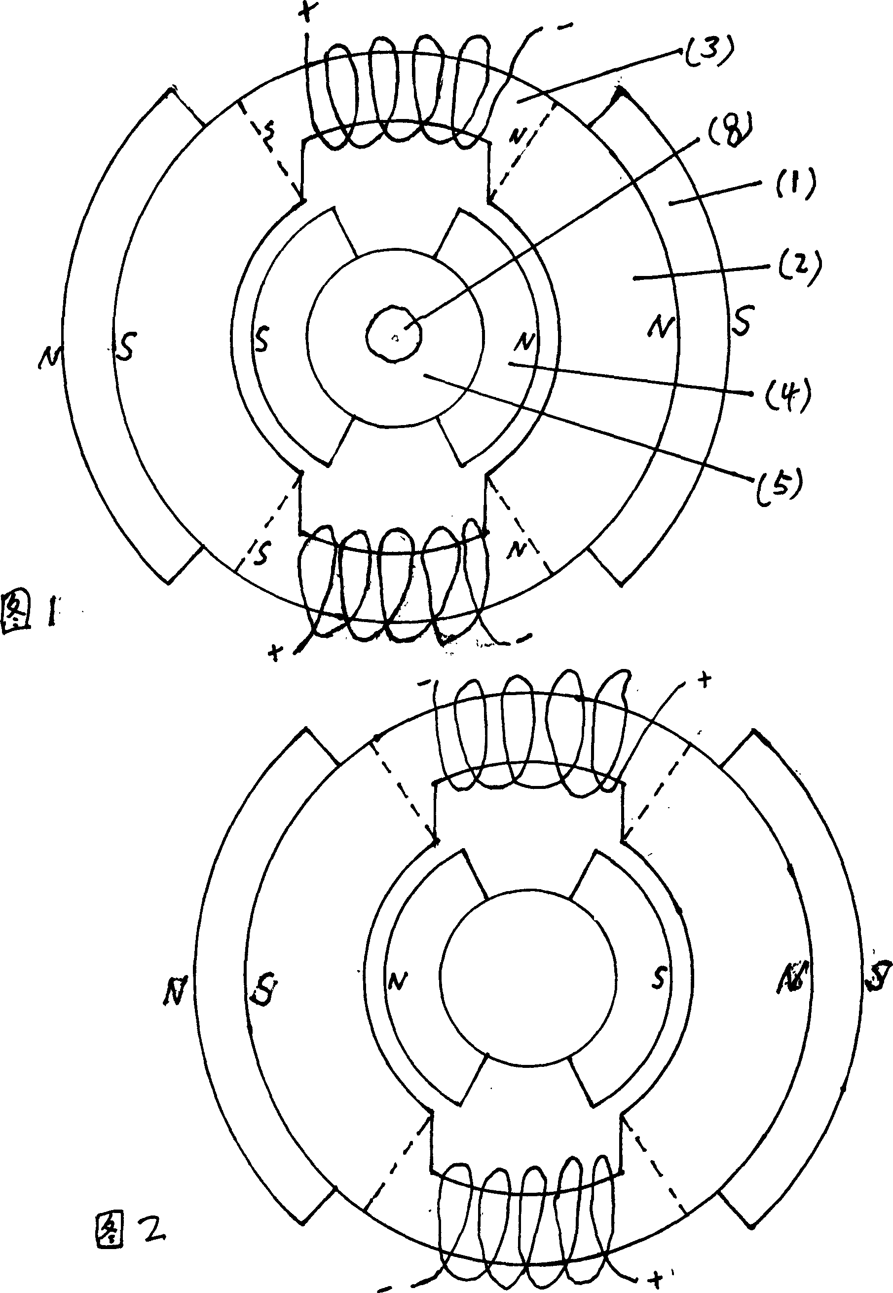
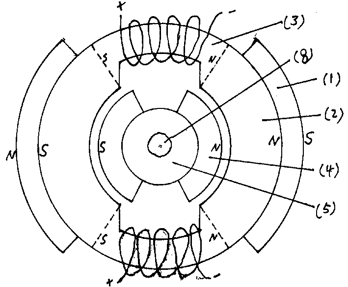
[0012] Figure 1 is a cross-sectional schematic diagram of one group of stators at the moment of power-on and the corresponding rotor. (1) represents the stator magnets, which are divided into two groups of four pieces, and the directions of the magnetic levels of the two groups are the same. The interval, (2) indicates the part corresponding to the stator core and the magnet, corresponding to the magnet (1) one by one, (3) indicates the electromagnet part of the stator, and forms the magnetic flux to (1) together with (2) when the power is off Closed loop, (4) represents the rotor magnet, (5) represents the rotor core, and (8) represents the main shaft.

[0013] Fig. 2 shows that relative to Fig. 1, another set of stators is at the moment of power failure and a schematic diagram of the rotor loading surface;

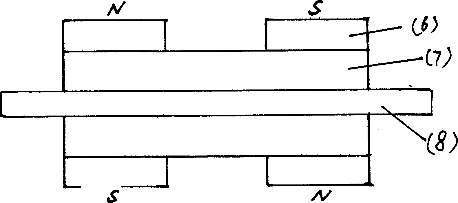
[0014] image 3 It shows the schematic diagram of the rotor surface passing through the rotor axis, (6) denotes the rotor magnet, (7) denotes the rotor core, and (8) den...


PUM


Abstract

This invented magnetic motor is composed of a permanent magnet, soft materials and electric magnetic coils, mainly for developing permanent magnetic energy to make the rotor rotate continuously, overcome loader resistance and transport mechanical energy to outside. The device uses soft magnetic materials to generate close action to magnetic flux of the stator magnet and uses DC electric magnet tostop the flux of the stator which two sets of magnetic poles circulate to generate a same way rotating force to the rotor magnetic pole to make the rotor rotate continuously and the power of this power source keeps constant along with it.

Description

technical field [0001] The invention relates to a motor, in particular to a magnetic motor with reasonable structure and high efficiency. Background technique [0002] The existing engine energy conversion process is complex and tortuous, with high cost, low efficiency and serious pollution. [0003] In view of this, how to provide a structural form that can minimize the unfavorable factors of the engine and maximize the use of energy with great potential to solve the problem of human energy demand and solve all polluting and unclean energy use problems It is the motivation of the present invention's research and development. [0004] The designer of the present invention relies on years of practical experience in fields such as technical research of various mechanical products and magnetic power research, and on the basis of repeated research and demonstration tests, a brand-new design structure is made, and finally the present invention is produced. [0005] Aiming at th...

Claims


Application Information

Patent Timeline
Patent Type & Authority Applications(China)
IPC IPC(8): H02K25/00H02K53/00
Inventor 王建功
Owner 王建功
Why Eureka
Try Eureka