Switching device

A switch device and a technology for adjusting switches, which are applied to power devices inside switches, electric switches, high-voltage/high-current switches, etc., can solve problems such as lack of flexibility in movable contact parts, and achieve intelligent and accurate control Effect

Inactive Publication Date: 2004-02-11
ABB POWER GRIDS SWITZERLAND AG
View PDF0 Cites 2 Cited by
  • Summary
  • Abstract
  • Description
  • Claims
  • Application Information

AI Technical Summary

Problems solved by technology

However, the known devices described above do not have sufficient flexibility to obtain optimum operation of the movable contact part

Method used


Image

  • Switching device
  • Switching device
  • Switching device

Examples


Embodiment Construction

[0056] The claimed invention will be described in detail below with reference to the accompanying drawings.

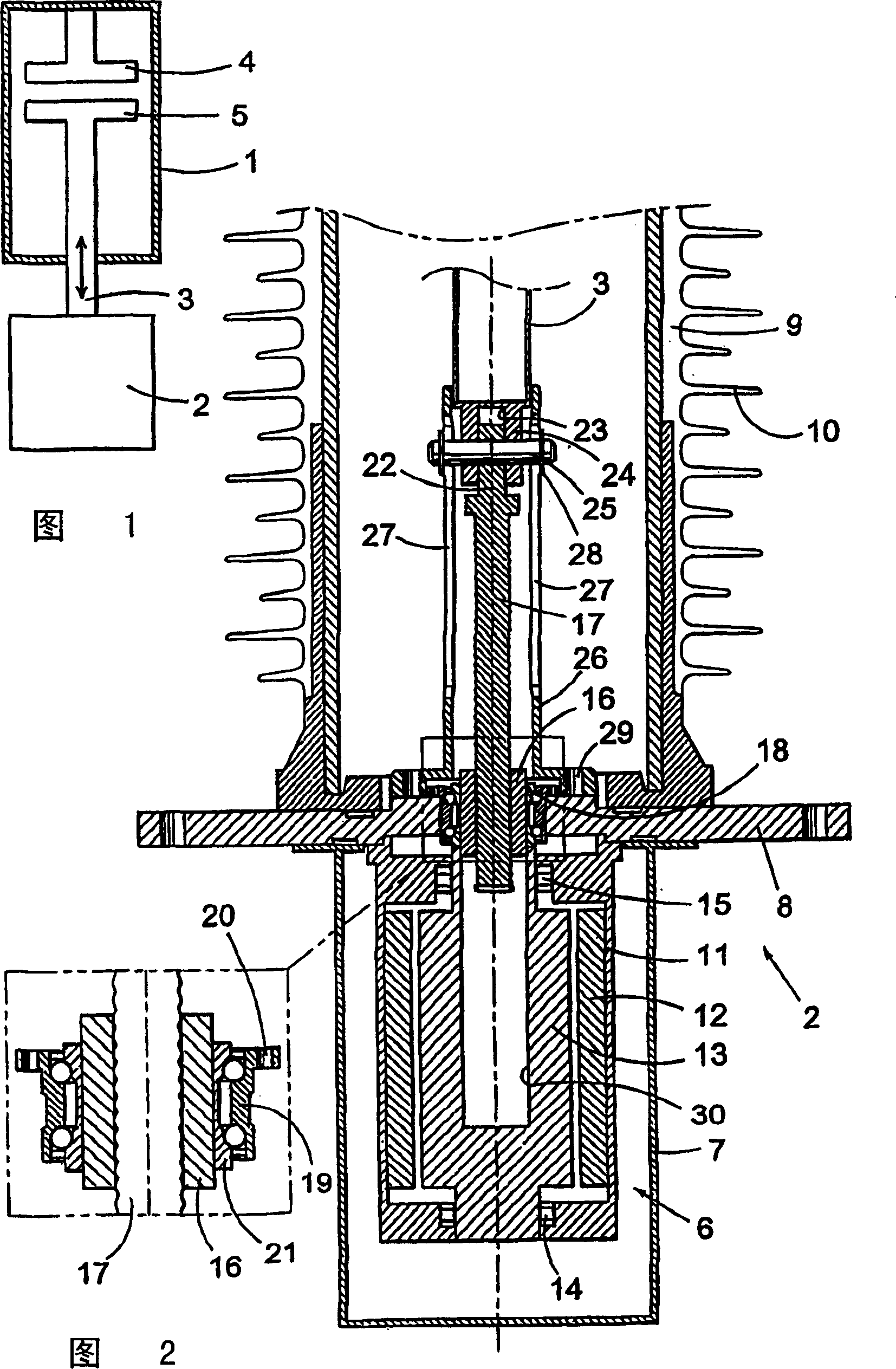
[0057] Fig. 1 schematically illustrates the elements of an electrical switching device. It includes a circuit breaker cavity 1, a driving device 2 and a driving rod 3. A fixed contact part 4 and a movable contact part 5 are provided in the circuit breaker cavity. Each contact part is respectively connected with the conductor. Under normal circumstances, the two contact portions 4, 5 are in contact with each other and current flows from one contact portion to the other contact portion through the switching device. When the current is interrupted for some reason, for example, due to a fault short-circuit current, the movable contact part 5 is moved away from the fixed contact part 4 at a high speed. Therefore, an arc is generated between the contact parts at first, and the arc disappears immediately after the contact parts are separated by the insulating gas. After that, whe...


PUM


Abstract

The present invention relates to a method for testing, controlling and regulating a switching device with contact parts, to a switching device and to a computer program therefore. The switching device comprises an electric motor (6) and a mechanical coupling device (41) for transforming motion from the electric motor to one of the contact parts (4, 5). Position, speed and / or acceleration of the contact part during operation are controlled during operation. By means of a control unit (43), the operation of the switching device is adaptively controlled in real-time. Storage means (70) are provided and contain information on measurements, events and failures in the switching device and include operation parameters. In the logs, information regarding self-diagnostic tests of the switching device can be stored as well.

Description

Technical field [0001] The invention relates to a method for testing, controlling and adjusting a switch device with a contact part, and relates to a switch device and a computer program thereof. The switch device includes a motor and a mechanical coupling device for performing movement conversion from the motor to at least one contact part. The switching device may include one or more motors and one or more mechanical coupling devices for performing movement conversion from the motors to the at least one contact part. During the operation, the position, speed and / or acceleration of at least one contact part are obtained, and the position, speed and / or acceleration of at least one contact part are controlled. The method and switchgear are especially intended for use in transmissions and high-voltage networks. Background technique [0002] Traditionally, the operation of the switching device is performed by using a spring mechanism with sufficient force to open and close the switc...

Claims


Application Information

Patent Timeline
Patent Type & Authority Applications(China)
IPC IPC(8): H01H33/59H01H3/26H01H11/00H01H33/36
CPCH01H3/264H01H11/0062H01H33/593H01H33/36
Inventor S·波斯加P·克耶尔M·贝克曼M·斯文松P·-O·图雷松L·荣松F·马努森P·拉松S·瓦尔德马松
Owner ABB POWER GRIDS SWITZERLAND AG
Why Eureka
Try Eureka