Crystal oscillator

A technology of crystal oscillators and capacitors, applied in the direction of power oscillators, electrical components, etc., can solve the problems of oscillation signal phase changes, center potential changes, etc., and achieve the effect of shortening time and reducing power consumption

Inactive Publication Date: 2004-02-25
上海创熙商贸有限公司
View PDF0 Cites 3 Cited by
  • Summary
  • Abstract
  • Description
  • Claims
  • Application Information

AI Technical Summary

Problems solved by technology

This achieves lower power consumption and shorter start-up time of oscillation operation, but since the voltage supplied to the logic inverter changes, the center potential of the output signal for the next stage changes
Since the threshold potential of the gate of the next stage is fixed, the problem caused by the change of the center potential is the phase change of the oscillation signal

Method used


Image

  • Crystal oscillator
  • Crystal oscillator

Examples


Embodiment Construction

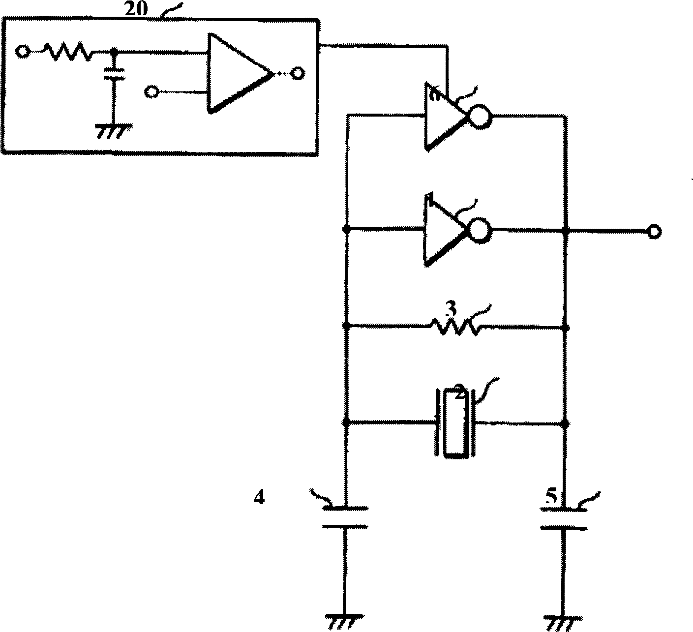
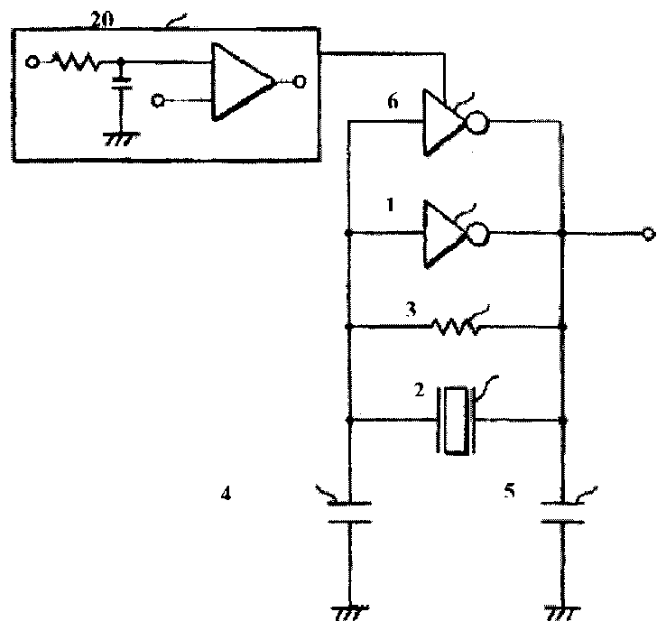
[0006] Such as figure 1 As shown, a crystal oscillator of the present invention includes a logic inverter 1 used as an amplifying element, a crystal oscillator 2, a feedback resistor 3, a gate capacitor 4, a source capacitor 5, and a three-state logic inverter buffer 6. It is characterized in that: the three-state logic inverter buffer 6 is forwardly connected in parallel to the logic inverter 1, so that it is only turned on and works for a fixed period of time during the oscillation start process. The feedback resistor 3 is connected to the crystal oscillator 2 in parallel, the logic inverter 1 is connected to the feedback resistor 3 in parallel, and the gate capacitor 4 and the source capacitor 5 are respectively connected to the Gate and source of logic inverter 1.

[0007] The working process of the present invention is described as follows: when the power is turned on, the crystal oscillator starts to oscillate. During the start-up of the oscillation, in response to a s...


PUM


Abstract

The present invention relates to a crystal oscillator, including logical inverter as amplification element, crystal oscillator, feedback resistor, grid capacitor, source capacitor tristate logical inverter buffer. The described tristate logical inverter buffer is forward parallelly-connected to the described logical inverter, the described feedback resistor is parallelly-connected to the described crystal oscillator, the described logical inverter is parallelly-connected to the feedback resistor, and the described grid capacitor and source capacitor are respectively connected to the describedgrid and source of logical inverter. The described logical inverter, only in the conduction time of starting oscillation, makes the oscillator continue oscillation according to the gani of logical inverter.

Description

Technical field: [0001] The present invention relates to an oscillator, and more particularly, to a low power consumption crystal oscillator having a short oscillation start-up time. Background technique: [0002] In a crystal oscillator, the time from starting oscillation to stable oscillation is longer than that in an RC oscillator. The method used in the prior art to shorten the oscillation start-up time of a crystal oscillator is to set a parallel circuit of a switching element and a resistor connected between the current-controlled crystal oscillator and a power supply. When the power is turned on, the switching element is placed in a conducting state, so that the voltage supplied to the oscillator increases. At a moment after a fixed period of time and when the oscillator is stable, the switching element is turned off, thereby reducing the supplied voltage. Although this achieves reduction of power consumption and shortening of start-up time of oscillation operation,...

Claims


Application Information

Patent Timeline
IPC IPC(8): H03B5/36
Inventor 范兴军
Owner 上海创熙商贸有限公司
Why Eureka
Try Eureka