
Plasma display

A plasma and display technology, which is applied to instruments, identification devices, cold cathode tubes, etc., can solve the problems of reducing the red brightness of the second display unit 32R, increasing manufacturing, and inconsistent operating voltage amplitudes, so as to avoid higher manufacturing accuracy. High, improve color temperature, reduce the effect of discharge area

Inactive Publication Date: 2004-03-03
AU OPTRONICS CORP
View PDF0 Cites 0 Cited by
  • Summary
  • Abstract
  • Description
  • Claims
  • Application Information

AI Technical Summary

Problems solved by technology

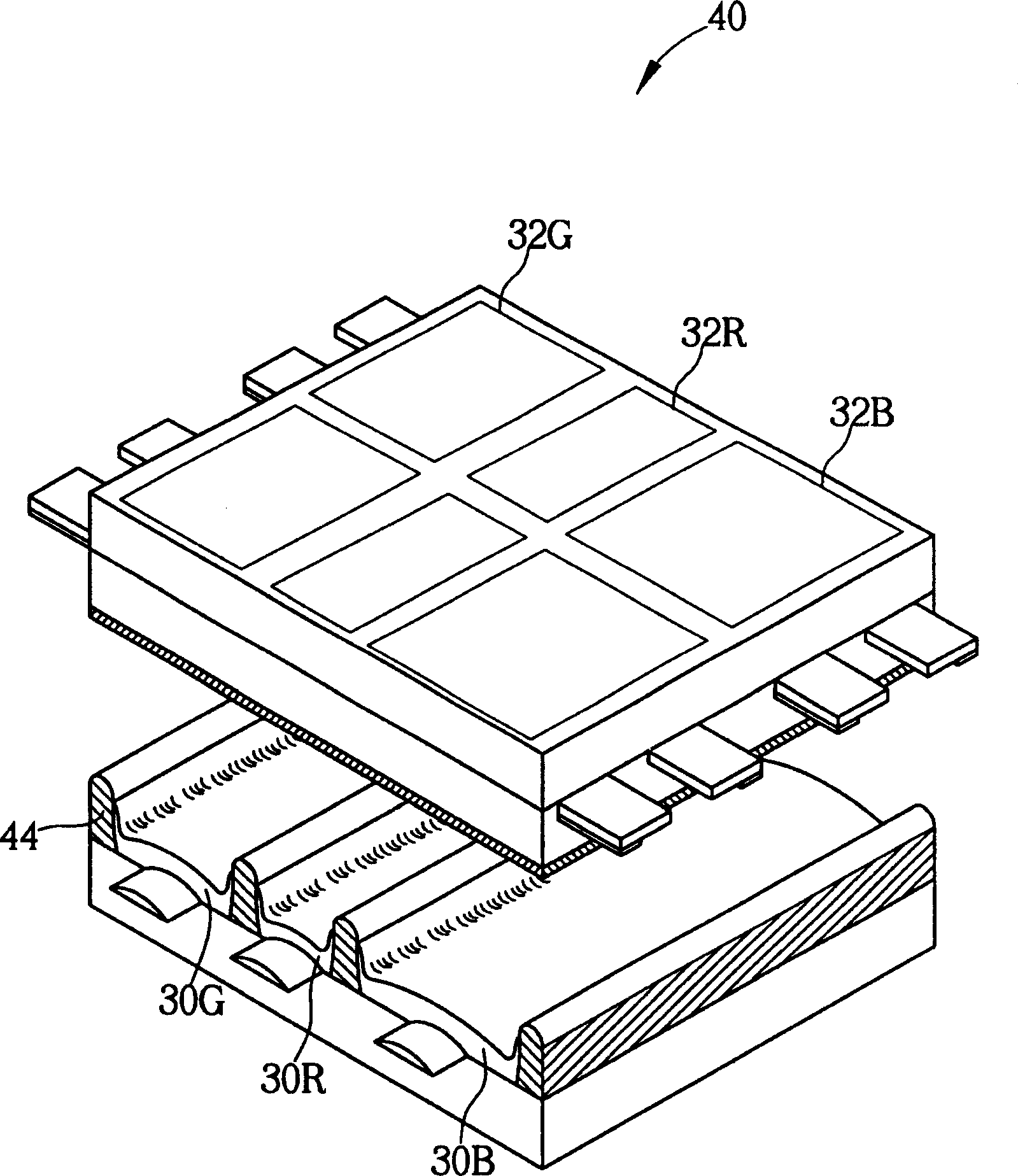
[0008] However, since the spacing of the barrier ribs 44 of the plasma display 40 is not uniform, part of the barrier ribs 44 must be made smaller than the spacing of the barrier ribs 24 of the plasma display 10 at the same resolution, which means that the manufacturing accuracy must be increased to produce a smaller pitch barrier wall 44
Generally speaking, the distance between the barrier walls covering the blue phosphor 30B must be more than 20% larger than that of the green 30G and red 30R, in order to have the effect of significantly improving the color temperature. Now that the resolution requirements are getting higher and higher, this This solution will increase the difficulty of manufacturing
In addition, since the plasma display 40 greatly reduces the discharge space of the second display unit 32R to reduce the red brightness of the second display unit 32R, the overall luminous efficiency of the plasma display 40 will be reduced.
On the other hand, since the distance between the barrier walls 44 of the plasma display 40 is different, the discharge spaces of the first display unit 32B, the second display unit 32R, and the third display unit 32G are different, so the operating voltage range of each display unit ( operational voltagemargin) inconsistencies

Method used


Image

  • Plasma display
  • Plasma display
  • Plasma display

Examples


Embodiment Construction

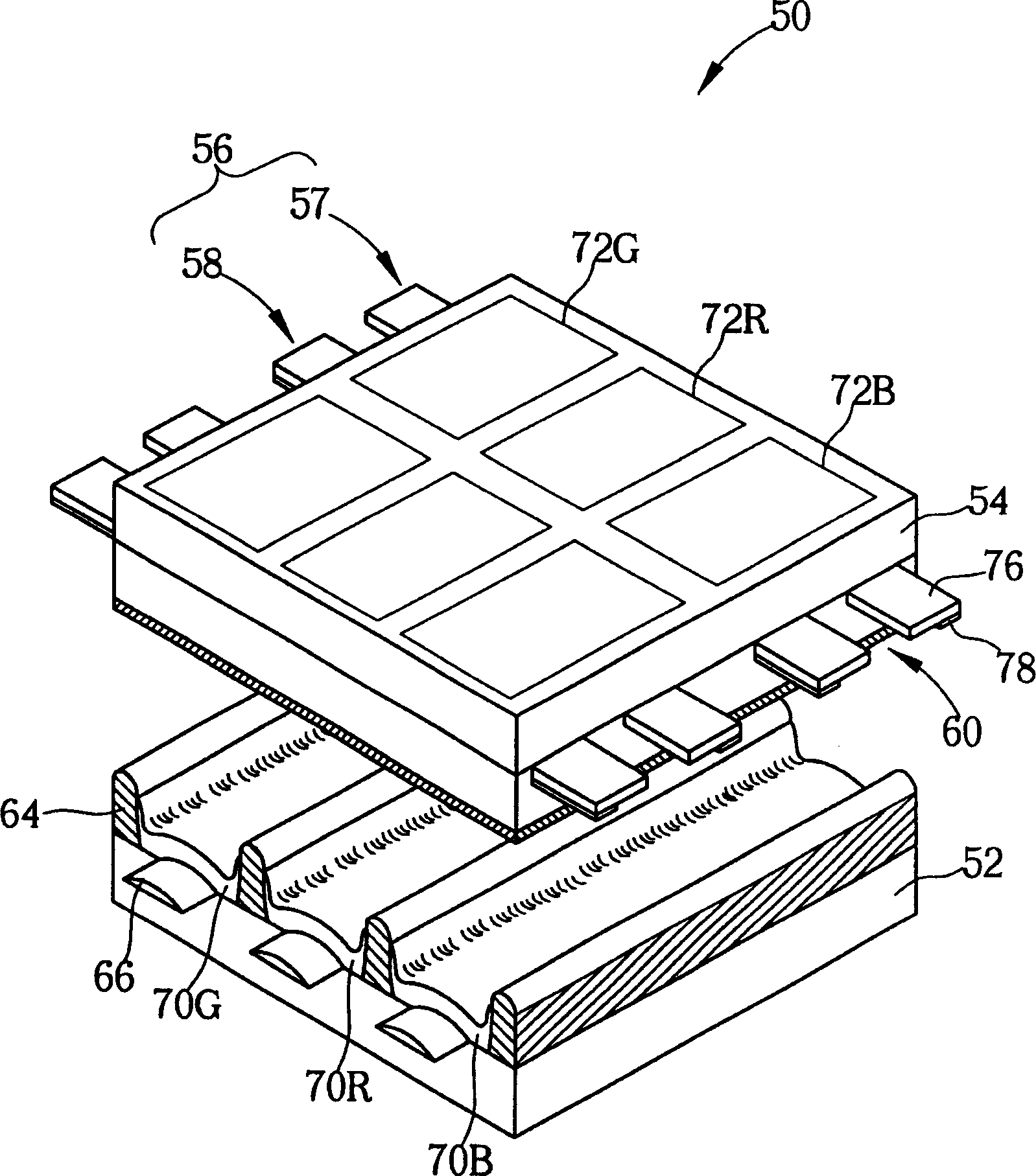
[0036] The invention provides a plasma display which changes the electrode area to increase the color temperature. Please refer to image 3 , image 3 It is a schematic diagram of the plasma display 50 of the present invention, each component and the constituent materials of the plasma display 50 and figure 1 The prior plasma display 10 shown is the same. Such as image 3 As shown, the plasma display includes a rear plate 52 and a front plate 54 arranged in parallel on the rear plate 52, and a plurality of electrode pairs (electrode pair) 56 are arranged on the lower side of the front plate 54 in parallel along a first direction. A plurality of data electrodes 66 and barrier walls 64 are arranged parallel and equidistant on the upper side of the rear plate 52 along a second direction, and the second direction is perpendicular to the first direction.

[0037]Each electrode pair 56 further includes a common electrode (common electrode) 57 and a scan electrode (scan electrode...


PUM


Abstract

The display includes a back plate, a front plate setup above the back plate parallelly, multiple electrode couples and data electrodes. Each electrode couple including first clear electrode and second clear electrode setup below the front plate parallelly. Each data electrode setup on up side of the front plate and perpendicular to each electrode couples. The crossing points between data electrodes and electrode couples defines multiple display units. According to three colors, the multiple display units are divided into first, second and third display units. An electrode couple of second and third display unit includes at least a groove.

Description

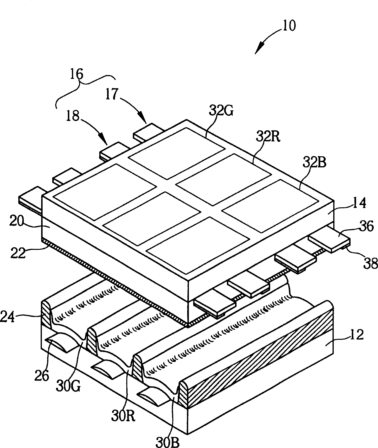
field of invention [0001] The invention relates to a plasma display, in particular to a plasma display which uses the area of ​​a transparent electrode to control the color temperature. Background technique [0002] Plasma displays have been gradually applied to large-size and large-area display devices. The principle of light emission is to generate ultraviolet light by driving plasma (plasma) through electrodes to irradiate the fluorescent body, so that the fluorescent body emits visible light. [0003] see figure 1 . figure 1 It is a schematic diagram of a conventional plasma display 10 . The conventional plasma display 10 includes a casing (not shown), and a rear panel 12 is installed on the rear panel 12 in parallel with a front panel 14 . The lower side of the front plate 12 is provided with a plurality of electrode pairs (electrode pair) 16, each electrode pair 16 includes a common electrode (common electrode) 17 and a scan electrode (scan electrode) 18, a dielectr...

Claims


Application Information

Patent Timeline
Patent Type & Authority Applications(China)
IPC IPC(8): G09F9/313H01J17/49
Inventor 简钰庭黄日锋
Owner AU OPTRONICS CORP
Learn More