New type series-parallel connected three degrees of freedom mechanism in pure rotational motion
A technology with a degree of freedom and pure rotation, applied to the parts of the instrument, instruments, etc., can solve the problems that are difficult to meet the design technical index requirements and small cross-sectional area, and achieve the effect of compact structure, small cross-sectional area and high rigidity
Inactive Publication Date: 2004-03-10
SHENYANG INST OF AUTOMATION - CHINESE ACAD OF SCI
View PDF0 Cites 5 Cited by
- Summary
- Abstract
- Description
- Claims
- Application Information
AI Technical Summary
Problems solved by technology
When a mechanism is required to realize the linkage of rotation around three coordinate axes, the rolling degree of freedom can realize continuous rotation, and the rotation range of the other two rotational degrees of freedom is not required, and the mechanism is required to have high rigidity and small cross-sectional area Under the above conditions, it is difficult to meet the design technical index requirements by adopting the above two forms respectively
Method used
View moreImage
Smart ImageViewing Examples

Examples
Embodiment 2
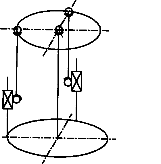
[0019] like image 3 Shown (slightly rotating joint 1) is a schematic diagram of the PSS type two-degree-of-freedom parallel mechanism of the present invention. The lengths of two connecting rods 2 with moving degrees of freedom are fixed, and one end thereof is slidably connected along a fixed guide rail slider.
Login to View More PUM
 Abstract
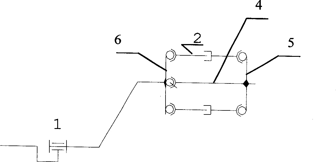
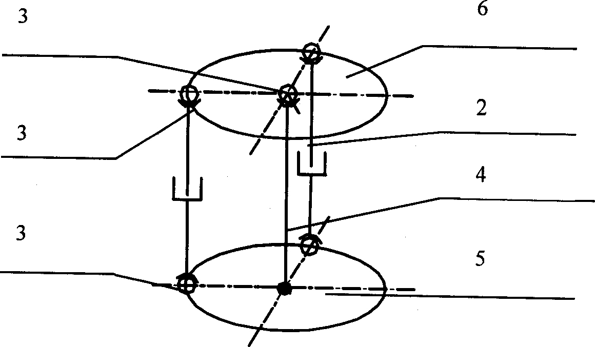
The mechanism consists of rotating joint, connecting bar possessing motion degree of freedom, central constraint pole, upper platform and lower platform. Revolving axis of the rotating joint is connected to the upper platform rigidly. One end of the central constraint pole is connected to the center of the lower platform rigidly, and the other end is connected to the upper platform through a ball pair. Two ends of two pieces of connecting bar possessing motion degree of freedom are connected to upper platform and lower platform through ball pairs, and distributed on a circle with a crossing point between the central constraint pole and platform being as circle center. The invention realizes interlocked rotations around three coordinate axes. Continuous turning can be realized in rolling degree of freedom, rotating range of other two-degree of rotational freedom is not large. The invented mechanism is utilized to application needed of high rigidity and small sectional area.
Description
technical field [0001] The invention relates to a three-degree-of-freedom pure-rotation mechanism, in particular to a novel series-parallel pure-rotation three-degree-of-freedom mechanism. Background technique [0002] There are many existing three-degree-of-freedom pure rotation mechanisms, which are mainly divided into two types. One is a series structure, that is, the rotation around three coordinate axes respectively; the other is a parallel structure, that is, most of them are based on the STEWART platform structure. Parallel motion platform and other structural forms. The above two forms have their own advantages and disadvantages and application occasions. When a mechanism is required to realize the linkage of rotation around three coordinate axes, the rolling degree of freedom can realize continuous rotation, and the rotation range of the other two rotational degrees of freedom is not required, and the mechanism is required to have high rigidity and small cross-sect...
Claims
Login to View More Application Information
Patent Timeline
 IPC IPC(8): G12B5/00
Inventor 徐志刚房立金王洪光陈书宏
Owner SHENYANG INST OF AUTOMATION - CHINESE ACAD OF SCI

PatSnap Eureka turns technology decisions into work you can execute. Powered by our Innovation Knowledge Graph, it runs expert workflows across engineering, life sciences, materials and intellectual property. Get your review-ready output in minutes.


