Axle driving buffer mechanism

A buffer mechanism and shaft transmission technology, applied in the direction of elastic element transmission, coupling, mechanical equipment, etc., can solve problems such as flameout, engine impact, loud noise, etc., to reduce noise and vibration, prolong service life, reduce impact effect

Inactive Publication Date: 2004-03-24
CHONGQING CHUANYU JINGGONG MACHINERY PARTS DEV
View PDF1 Cites 3 Cited by
  • Summary
  • Abstract
  • Description
  • Claims
  • Application Information

AI Technical Summary

Problems solved by technology

The shaft transmission device of this kind of engine, because its power output shaft and the differential of the rear axle are a kind of rigid connection, this rigid connection will change with the driving working conditions of the vehicle, such as speed up, shifting gears or bumps with the road surface, An alternating impact load is generated, and the recoil force formed by this alternating impact

Method used


Image

  • Axle driving buffer mechanism
  • Axle driving buffer mechanism
  • Axle driving buffer mechanism

Examples


Embodiment Construction

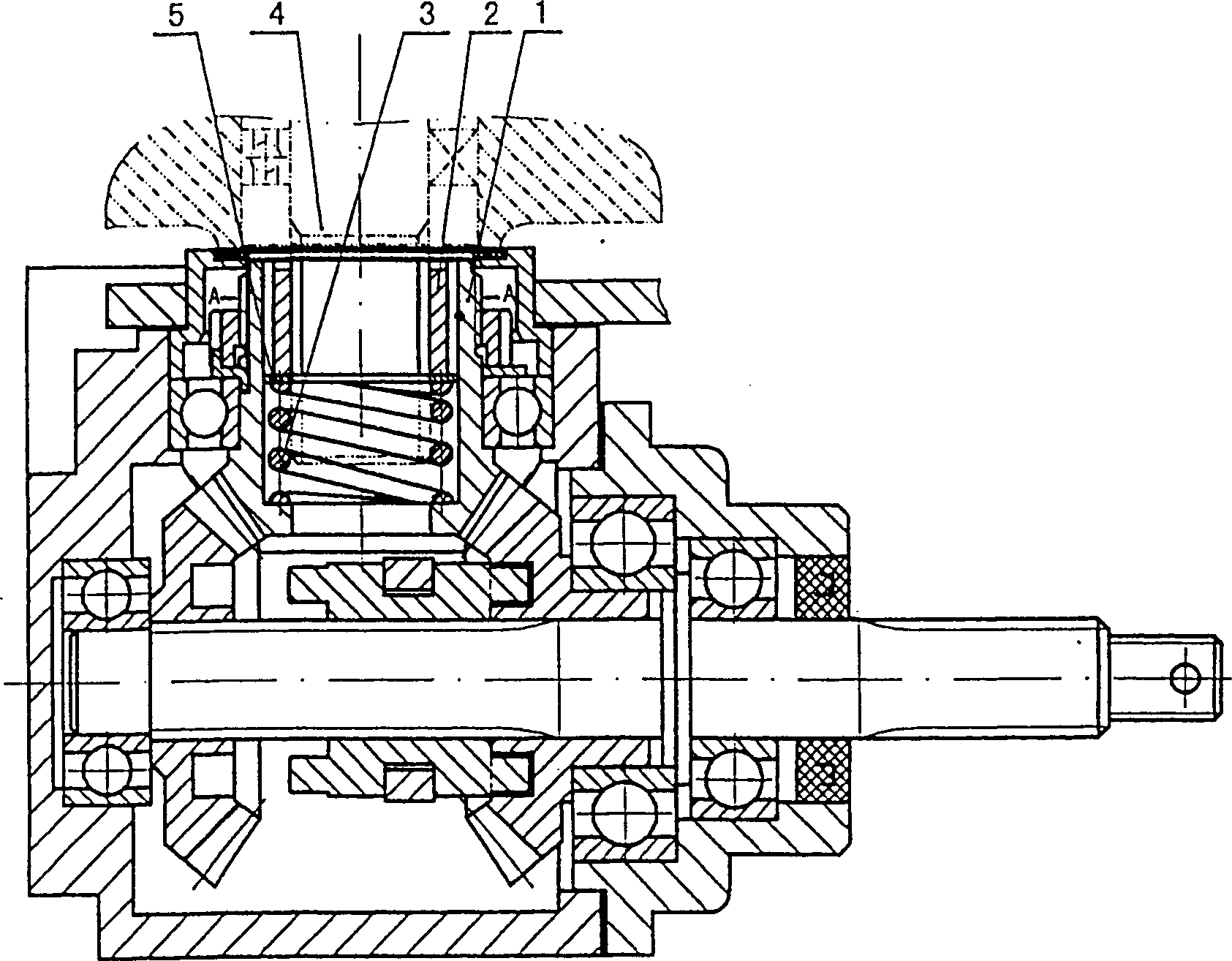
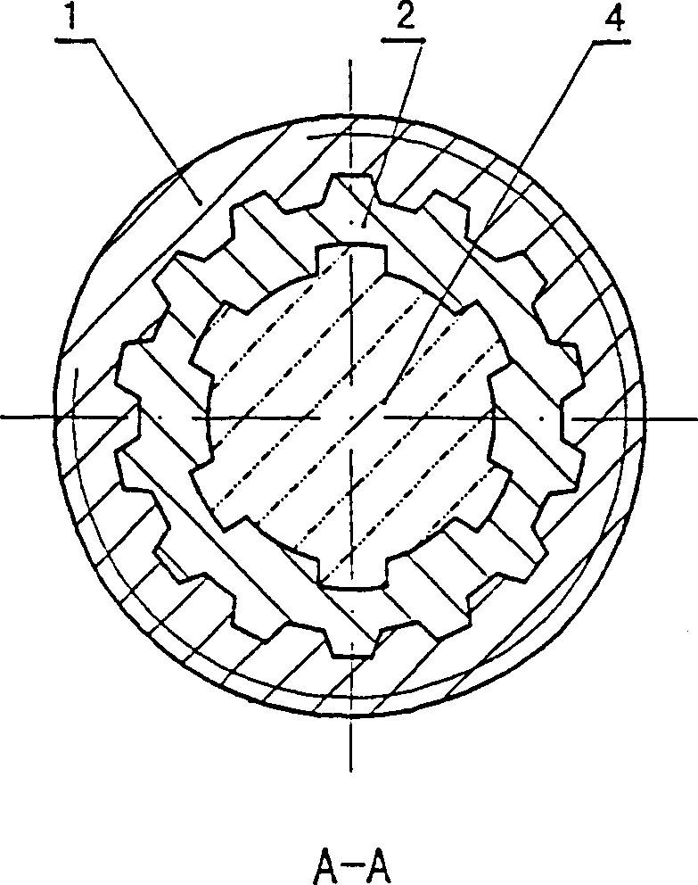
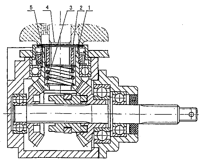
[0010] A shaft transmission buffer mechanism, characterized in that: a buffer mechanism is added between the power input shaft and the power output shaft; the buffer mechanism includes an inner sleeve 2, an outer sleeve and a pressure spring 3, wherein the power input shaft is assembled in the inner sleeve 2 of the buffer mechanism , the outer circle of the inner sleeve 2 is connected with the outer sleeve as the power output shaft by a helical tooth spline, and a compression spring 3 is arranged between the axial end face of the inner sleeve 2 and the inner end face of the outer sleeve.

[0011] Referring to the above-mentioned accompanying drawings, it can be seen that when the present invention is used in the motorcycle engine shaft drive reverse gear, the buffer mechanism is assembled between the engine output shaft 4 and the power input bushing 1 of the shaft drive, and the engine output shaft wherein 4 As the power input shaft, the power input shaft sleeve 1 of the shaft ...


PUM


Abstract

The present invention relates to a shaft transmission buffer mechanism, and is characterized by that between power input shaft and power output shaft a buffer mechanism is added, said buffer mechanism includes inner sleeve, external sleeve and press spring, in which the power input shaft is assembled in the inner sleeve, and the periphery of the inner sleeve and the external sleeve as power output shaft are connected by means of screwed tooth spline, and between the axial end face of the inner sleeve and inner end face of the external sleeve the press spring is placed. Said invention can eliminate the production of high-frequency resonance in power transferring process, and can implement the torque transferring flexible connection of shaft transmission, and can have buffer action.

Description

technical field [0001] The invention relates to a shaft transmission buffer mechanism, in particular to an engine shaft transmission buffer mechanism suitable for various motorcycles, such as two-wheel, three-wheel, four-wheel motorcycles and beach motorcycles. Background technique [0002] In the current shaft transmission device, the power input shaft and the power output shaft are often assembled directly. This direct assembly has a great impact on the power source of the shaft transmission device during the power transmission process. Take the engine shaft transmission of a motor vehicle as an example. , such as motorcycles and ATVs with three or more wheels, most of their engine output shafts are connected to the rear axle differential by a shaft transmission. ZL98228725.9 discloses "a kind of moped engine reverse gear", it is that the engine output shaft is directly assembled with the active spline bevel gear, and the active spline bevel gear assembled by the engine ou...

Claims


Application Information

Patent Timeline
IPC IPC(8): B62M21/00F16D3/00
Inventor 付置贵高同大
Owner CHONGQING CHUANYU JINGGONG MACHINERY PARTS DEV
Why Eureka
Try Eureka