Method for testing coupling property of magnetic suspension rotor system and tesl platform

A technology of magnetic levitation rotor and test method, which is applied in the direction of measuring device, magnetic variable measurement, instrument, etc., and can solve the problems that have not been seen in the report of the test bench for the coupling characteristics of the magnetic levitation rotor system.

Inactive Publication Date: 2004-03-24
WUHAN UNIV OF TECH
View PDF0 Cites 23 Cited by
  • Summary
  • Abstract
  • Description
  • Claims
  • Application Information

AI Technical Summary

Problems solved by technology

[0004] At present, there is no report on the test bench for the

Method used


Image

  • Method for testing coupling property of magnetic suspension rotor system and tesl platform
  • Method for testing coupling property of magnetic suspension rotor system and tesl platform
  • Method for testing coupling property of magnetic suspension rotor system and tesl platform

Examples


Embodiment Construction

[0021] The present invention will be further described below in conjunction with example and accompanying drawing.

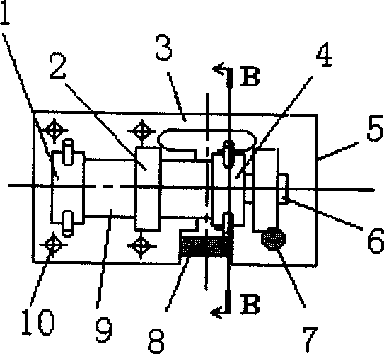
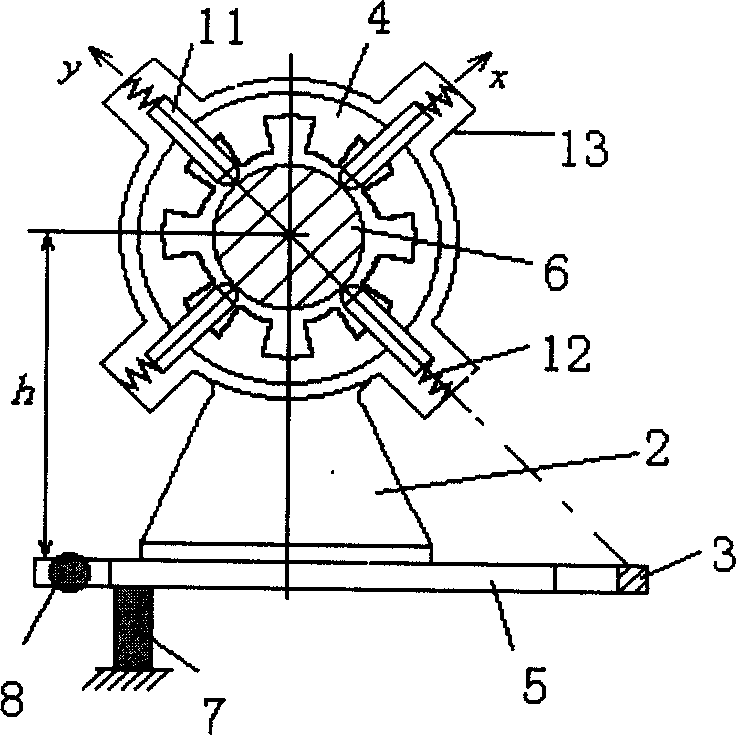
[0022] The inventors have found through research on the coupling of the magnetic levitation rotor system that: in the magnetic levitation rotor system, the coupling force of the radial magnetic bearing is caused by the eccentricity of the rotor, while the coupling torque is caused by the tilt of the rotor. Therefore, testing the coupling force and coupling torque to simulate the eccentricity and inclination of the maglev rotor is the key to the problem. Suspension force F yy Coupling force F at eccentricity at 90° and 270° yx = 0, that is, there is no coupling force on the y-axis; the suspension force F xx Coupling force F at eccentricity at 0° and 180° xy =0, that is, there is no coupling force on the x-axis. But there are coupling forces when the eccentricity is in other orientations. This phenomenon can be defined as: the non-superposition of the magneti...


PUM


Abstract

The invention is a testing method of the coupled property of the magnetic suspension rotor system and the test table. It uses non-superposition of magnetic bearing's magnetic forces and superpositionof the displacement to get coupled parameters such as coupled force, coupled torque, etc, and determine the relationship of the suspension forces of the magnetic pole pair in x or y direction of the magnetic bearing and the currents, namely magnetic pole suspension force-current property curve family. It uses computer to control thermal expansion extension of expansion shaft, to make the deformation beam elastically deform and further simulates micro eccentricity and tilt of rotor to design the test table, namely the whole electric control system.

Description

technical field [0001] The invention relates to the technical field of magnetic levitation, in particular to a test method and a test bench for the coupling characteristics of a magnetic levitation rotor system. Background technique [0002] The magnetic levitation rotor system is a product of magnetic bearing technology, which has the advantages of magnetic bearing and is a high-tech product of mechanical and electrical integration. The magnetic bearing can stably suspend the supported part in the space without any mechanical contact between the supporting part and the supported part. Compared with traditional bearings, it has the following main advantages: no contact, no wear, and the bearing life is theoretically unlimited; high speed, the highest line speed can reach 200m / s; no lubrication and sealing, no environmental pollution; low power consumption , energy saving; high precision, anti-vibration, no noise; easy to realize various intelligent controls. [0003] Accor...

Claims


Application Information

Patent Timeline
IPC IPC(8): G01R33/00
Inventor 胡业发王晓光周祖德江征风
Owner WUHAN UNIV OF TECH
Why Eureka
Try Eureka