Image process apparatus
An image processing device and image processing technology, applied in image data processing, image enhancement, image analysis, etc.
- Summary
- Abstract
- Description
- Claims
- Application Information
AI Technical Summary
Problems solved by technology
Method used
Image
Examples
no. 1 example
[0055] First, refer to Figure 1-11(b) , the first embodiment of the present invention will be described.
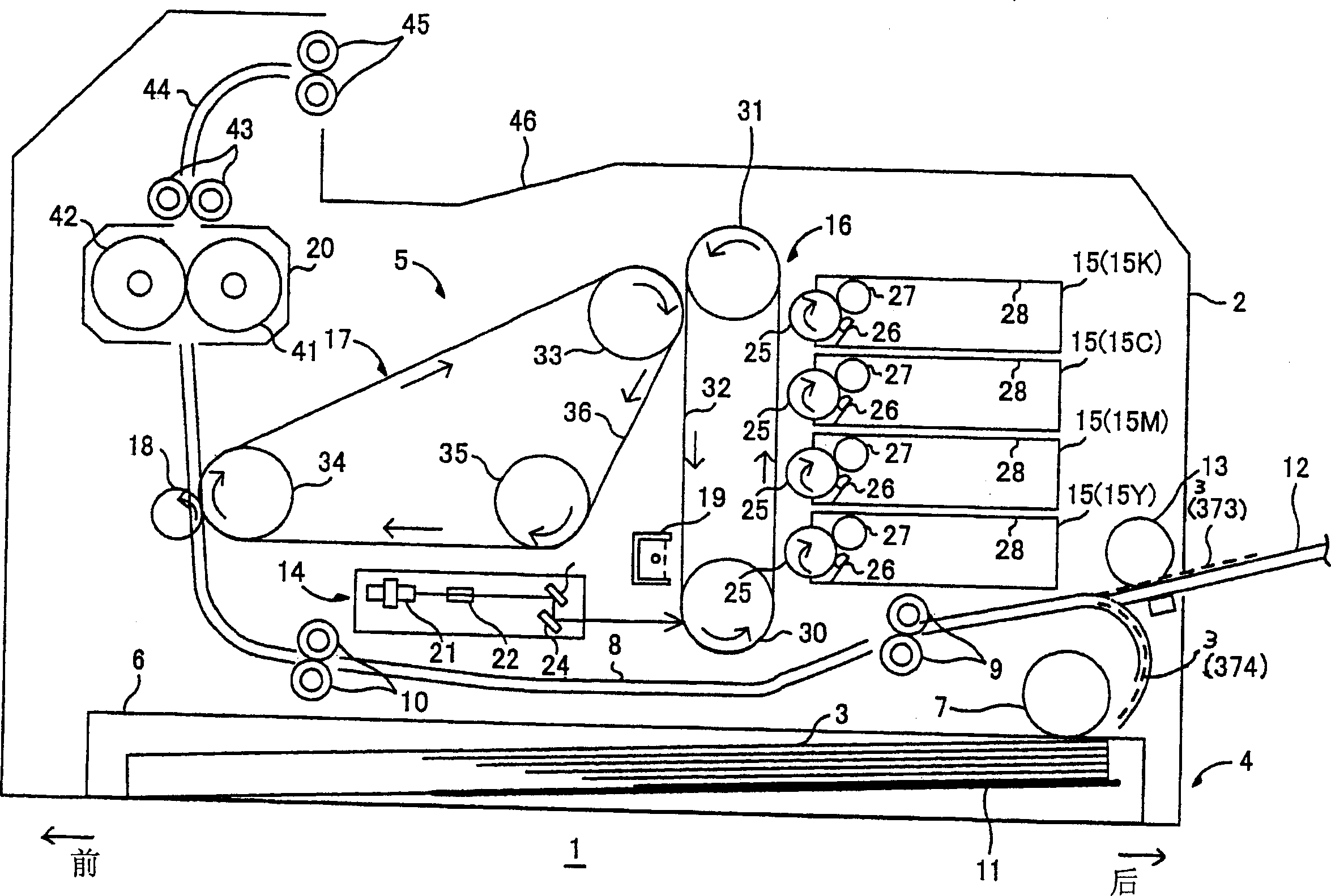
[0056] figure 1 is a side sectional view showing relevant parts of the color laser printer 1 in the preferred embodiment. Such as figure 1 , the color laser printer 1 comprises: a main casing 2, in the main casing 2, a feeding unit 4 supplies paper 3 as a recording medium, an imaging unit 5 forms an image on the paper 3 provided by the feeding unit 4, and other devices.
[0057] Feeding unit 4 comprises: a paper feed tray 6 that is removably mounted on the bottom of the main housing 2, a feed roller 7 mounted on one side of the paper feed tray 6 (thereafter, the feed roller 7 of the main housing 2 is equipped with One side is called the back side, and the side with the delivery roller 18 mentioned later is called the front side), a paper feeding path 8, and a pair of feeding rollers 7 downstream of the feeding roller 7 in the direction of supplying the paper 3 in the...
no. 2 example
[0193] The following will refer to Figure 12-17(b) A second embodiment of the present invention will be described.
[0194] The difference between the second embodiment and the first embodiment lies in the display contents of the color-blindness dialog 66 and the page processing (image processing process) for printing.
[0195] According to this embodiment, if Figure 12 As shown, the color-blind dialog box 66 is similar to the first embodiment (such as Figure 4 ) includes a colorblind processing mode selection box 67. But the color blind dialog box 66 does not include the color blindness type setting column 68 and the color blindness degree setting column 69 in the first embodiment, but includes an image processing object setting column 168 and an image processing method setting column 169 .
[0196] The image processing target setting column 168 lets the user set conditions for the target of color-blind image enhancement processing. More specifically, the image process...
no. 3 example
[0231] The following will refer to Figure 18-24(b) A third embodiment of the present invention will be described.
[0232] The third embodiment is also different from the first embodiment in that the display content of the color blind dialog box 66 and the printed page processing (image processing process) are different.
[0233] Such as Figure 18 As shown, according to this embodiment, the color-blind dialog box 66 includes the same as the first embodiment ( Figure 4 ) similar color blindness processing mode selection box 67. However, the color blind dialog box 66 does not have the color blindness type setting bar 68 and the color blindness degree setting bar 69 of the first embodiment, but includes a split print setting bar 268 for selecting whether to print on separate sheets of paper 3 according to color distinction color image. And a monochrome printing setting field 269 for selecting whether to print the image of each color.
[0234] The split print setting colum...
PUM
 Abstract
Description
Claims
Application Information
 - R&D
- Intellectual Property
- Life Sciences
- Materials
- Tech Scout
- Unparalleled Data Quality
- Higher Quality Content
- 60% Fewer Hallucinations
Browse by: Latest US Patents, China's latest patents, Technical Efficacy Thesaurus, Application Domain, Technology Topic, Popular Technical Reports.
© 2025 PatSnap. All rights reserved.Legal|Privacy policy|Modern Slavery Act Transparency Statement|Sitemap|About US| Contact US: help@patsnap.com


