Hydraulic and pneumatic operative diaphragm valve

A diaphragm valve and hydraulic technology, applied in the field of controlling fluid flow, can solve the problems of increased fluid waste and inconvenient use

Inactive Publication Date: 2004-04-07
辛在贤
View PDF0 Cites 13 Cited by
  • Summary
  • Abstract
  • Description
  • Claims
  • Application Information

AI Technical Summary

Problems solved by technology

However, this fluid control valve also has the following disadvantages, since the lever is arranged at the upper end of the valve body and thus the lever must be manipulated each time the fluid passage is opened and closed, it is inconvenient to use and causes increased fluid waste

Method used


Image

  • Hydraulic and pneumatic operative diaphragm valve
  • Hydraulic and pneumatic operative diaphragm valve
  • Hydraulic and pneumatic operative diaphragm valve

Examples


Embodiment Construction

[0028]Preferred embodiments of the invention, examples shown in the accompanying drawings, will be described in detail below. The same reference numerals are used throughout the drawings and specification to designate the same or equivalent parts.

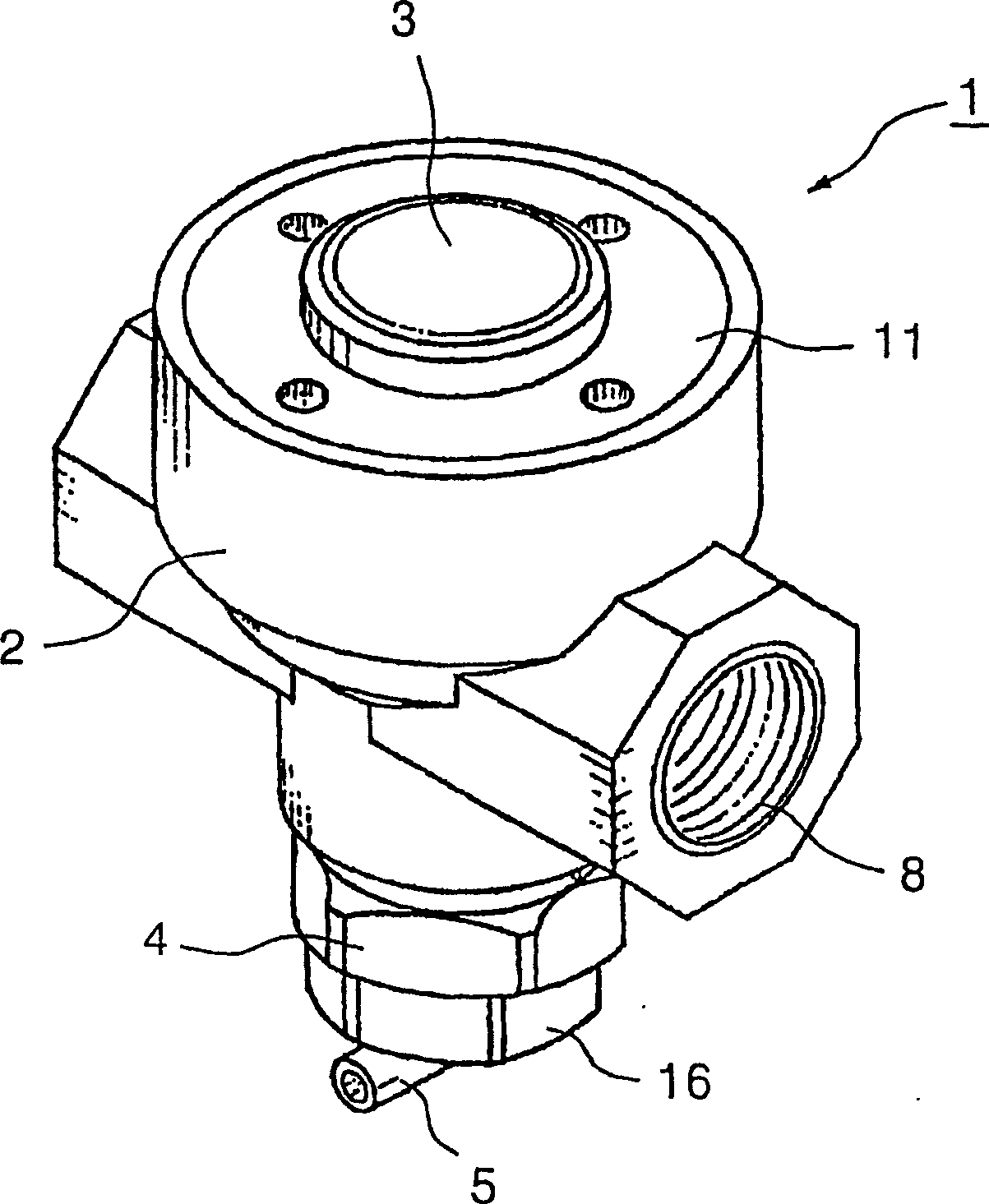
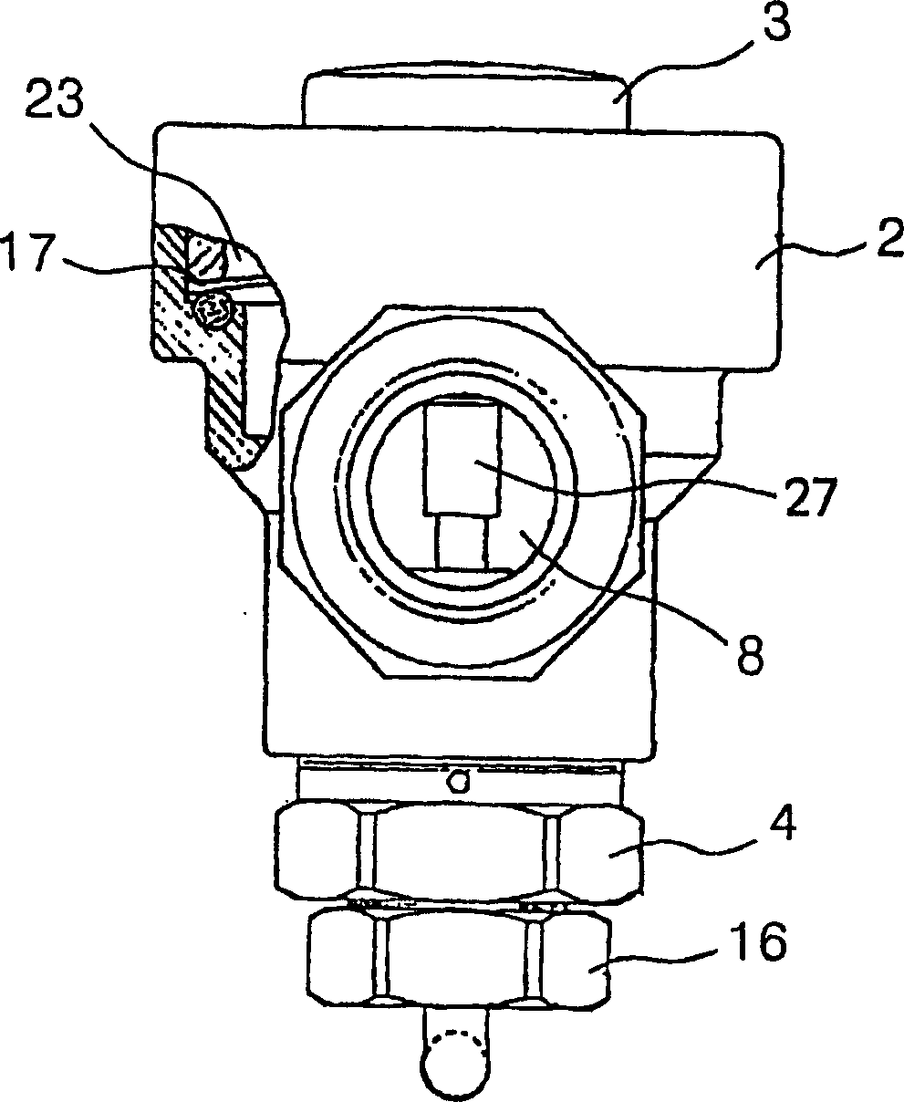
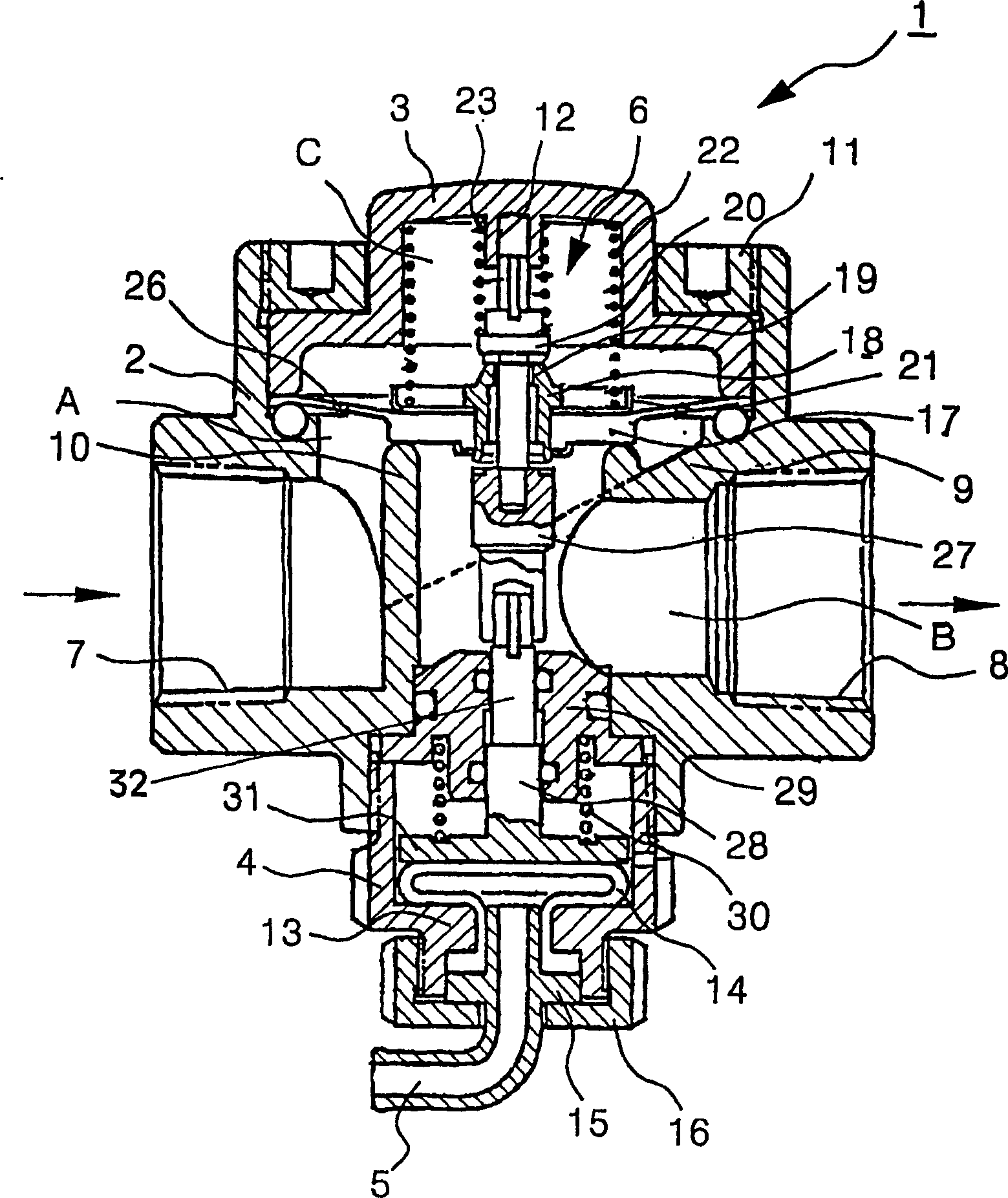
[0029] refer to Figures 1 to 4 , denotes a hydraulically and pneumatically operated diaphragm valve according to a first embodiment of the invention. A hydraulically and pneumatically operated diaphragm valve denoted by reference numeral 1 includes a valve housing 2, a cover 3, a retainer 4, a button 5, a fluid control device 6, and a power transmission device. The valve housing 2 is provided with a fluid channel. The cover 3 closes the upper end opening of the valve housing 2 . A retainer 4 is installed in the lower end opening of the valve housing 2 . The button 5 has the structure of a tubular part such that a pocket part 14 fixedly received in the holder 4 is connected to one end of the tubular part, and the other end of t...


PUM


Abstract

Disclosed is a diaphragm valve. When a chamber is expanded by fluid supply into a pipe-shaped button, a valve stem is slightly moved upward by a rod and a shaft to open an outlet of an orifice. Fluid received in a space between a cap and a diaphragm and having a high pressure is discharged into an outlet-side space, whereby the diaphragm opens a guide conduit. When fluid is discharged from the pipe-shaped button, the diaphragm is moved toward the guide conduit, and the valve stem closes the outlet. The fluid in the inlet-side space has a high pressure, and the fluid in the space between the cap and diaphragm has a low pressure. The high pressure fluid flows toward the low pressure fluid through a pilot hole of the diaphragm. When fluid pressure balance is effected between the spaces, the diaphragm closes the guide conduit.

Description

technical field [0001] The present invention relates to a diaphragm valve utilizing a diaphragm to control fluid flow, and more particularly, the present invention relates to a hydraulically and pneumatically operated diaphragm valve constituting a bladder which allows a diaphragm to communicate with a push button. member) opens a flow channel when the cavity of the pouch member is inflated, and closes the flow channel when the cavity of the pouch member returns to its original state, thereby achieving hydraulic and Liquid flow is controlled pneumatically and therefore does not require the use of solenoid valves. In hydraulically and pneumatically operated diaphragm valves, the button that operates the diaphragm is sealed when the working fluid is contained therein, so that when the button is pressed, the chamber of the pouch that communicates with the button inflates, and when the button is released, the chamber of the pouch member returns to its original state, so that as t...

Claims


Application Information

Patent Timeline
Patent Type & Authority Applications(China)
IPC IPC(8): F16K7/16F15B7/00F16K7/17F16K31/12F16K31/145F16K31/385F16K31/62
CPCF15B7/00F16K31/12F16K31/62F16K31/3855
Inventor 辛永勋
Owner 辛在贤
Why Eureka
Try Eureka