
Communication error detecting method for vehicular bus communication network

An error detection, communication network technology, applied in vehicle testing, bus network, error prevention and other directions, can solve problems such as failures

Inactive Publication Date: 2004-05-12
MITSUBISHI MOTORS CORP
View PDF1 Cites 4 Cited by
  • Summary
  • Abstract
  • Description
  • Claims
  • Application Information

AI Technical Summary

Problems solved by technology

Since this first type ECU performs communication error detection when the ignition key is in the start position (in general, corresponding to the on position), even if a countermeasure is provided to stop the communication error when the ignition key is in the off position detection, there may still be a risk that this second type ECU will be identified as malfunctioning

Method used


Image

  • Communication error detecting method for vehicular bus communication network
  • Communication error detecting method for vehicular bus communication network
  • Communication error detecting method for vehicular bus communication network

Examples


Embodiment Construction

[0030] A communication error detection method for a bus communication network according to an embodiment of the present invention will be described below with reference to the accompanying drawings.

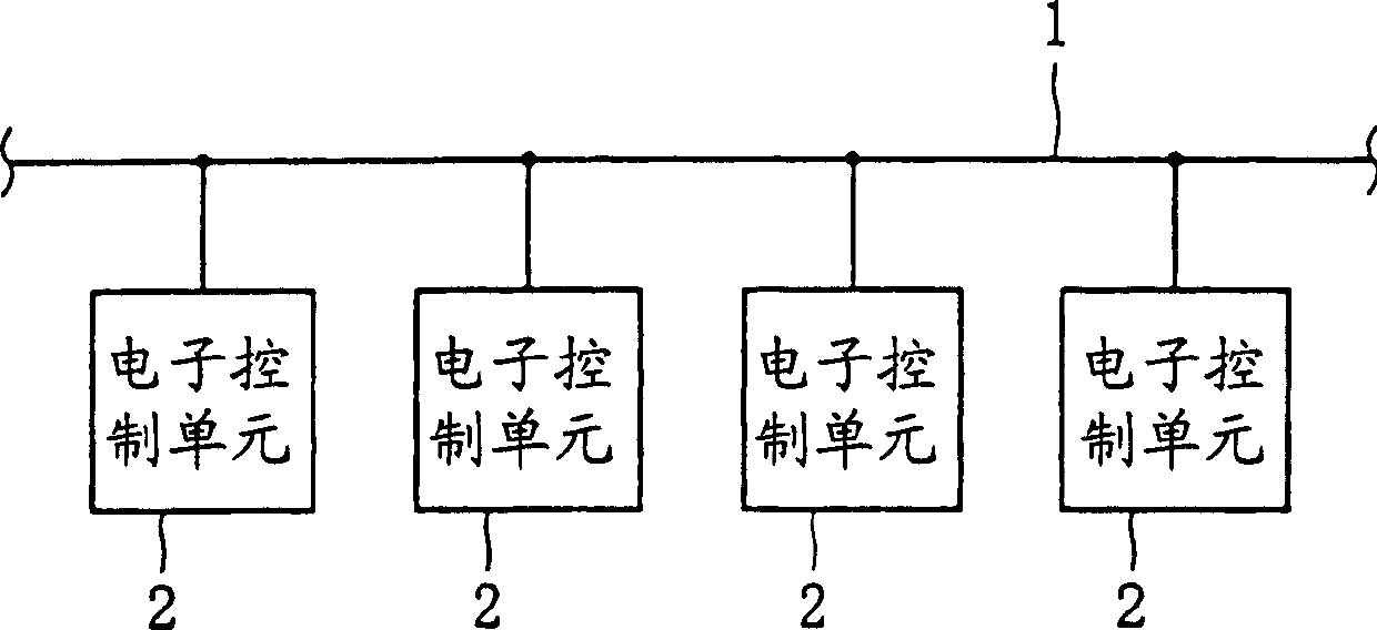
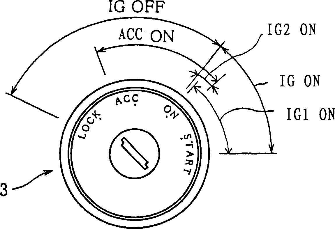
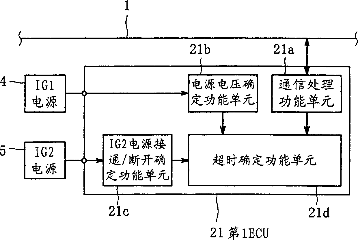
[0031] As shown in Figure 1, the vehicle bus communication network that has applied the communication error detection method according to the embodiment of the present invention has a plurality of ECUs 2 connected to the bus 1 as the multiplexing transmission path (Figure 1 shows a plurality of ECUs 4 ECUs). Each ECU is constituted by a first type, a second type or a third type ECU (hereinafter referred to as first to third ECU). Here, as shown in FIG. 2 , the conditions under which the first to third ECUs are powered on and off depending on the ignition key position are different from each other. In this regard, the IG1 power supply, the IG2 power supply, and the auxiliary equipment (ACC) power supply are connected to the battery (not shown) through, for example, the ignition s...


PUM


Abstract

A communication error detecting method for a bus communication network including a first type ECU which is powered on whether an ignition key is situated at an ON position or a cranking position and a second type ECU which is powered on when the ignition key is situated at the ON position and which is powered off when the ignition key is situated at the cranking position. The communication error detecting method includes: selecting a predetermined detecting mode from a plurality of detecting modes according to a combination of the type of a subject ECU and the type of a corresponding ECU; and performing an error detection according to the predetermined communication error detecting mode so selected.

Description

technical field [0001] The invention relates to a communication error detection method of a bus communication network in a vehicle. Background technique [0002] Generally, a plurality of electronic control units (ECUs) that control a plurality of actuators electronically are mounted on a vehicle. Each ECU electronically controls actuators connected to the ECU concerned, while transmitting and receiving data between the ECU concerned and the corresponding ECU by communicating using a multiplexed transmission path. [0003] When an abnormality occurs in the ECU or the multiplex transmission path in such a vehicle multiplex communication system, data transmission cannot be performed between the ECUs, or data transmission may be erroneously performed. Therefore, there is a concern that electronic control cannot be performed correctly. In order to solve this problem, a communication error detection function is generally provided for each ECU for determining an abnormality exis...

Claims


Application Information

Patent Timeline
Patent Type & Authority Applications(China)
IPC IPC(8): G01M17/007B60R16/02B60R16/023B60R16/03H04L1/00H04L12/40
CPCB60R16/0315H04L1/00
Inventor 佐野喜亮早瀬宪児深谷俊树阿部俊之
Owner MITSUBISHI MOTORS CORP
Learn More