

Backlight source and liquid crystal display device
A liquid crystal display device and backlight technology, which is applied in the field of backlight, can solve the problems of insufficient brightness and uneven brightness of surface light sources, and achieve the effect of uniform brightness
- Summary
- Abstract
- Description
- Claims
- Application Information
AI Technical Summary
Problems solved by technology
Method used
Image

Examples
no. 1 approach
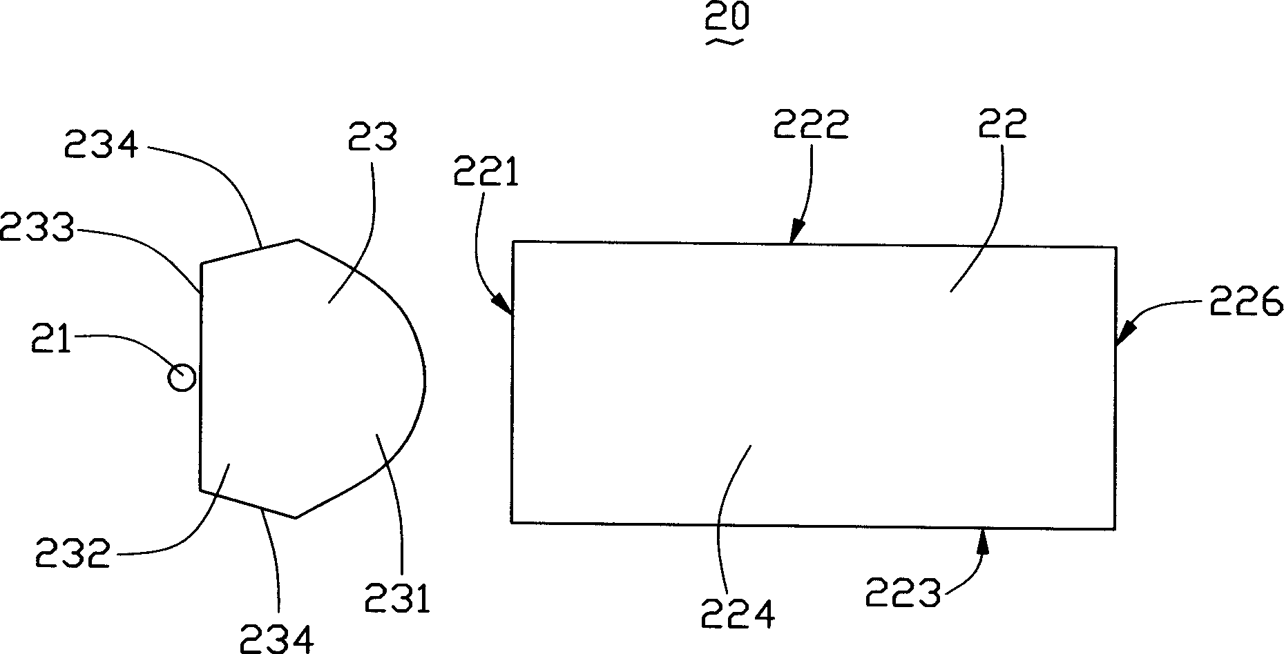
[0018] please see image 3 , the first embodiment of the backlight of the present invention, the backlight 20 includes a plurality of light emitting diodes 21 and a light guide plate 22, a plurality of microlenses 23 are arranged between the light emitting diodes 21 and the light guide plate 22, and the plurality of The light-emitting diodes 21 and the light guide plate 22 are respectively positioned within the working distance of the left and right sides of the plurality of microlenses 23 (described later), so that the microlenses 23 couple the divergent light emitted by the plurality of light-emitting diodes 21 into uniform parallel light incident into the light guide plate 22.
[0019] The light guide plate 22 is roughly a cuboid plate entity, which includes a light incident surface 221 adjacent to the microlens 23, a light exit surface 222 perpendicular to the incident surface 221, a bottom surface 223, a first side (not shown), and a second One side is opposite to the se...
PUM
 Abstract
Description
Claims
Application Information