Beam connecting structure in house

A technique of building and structure, which is applied in the field of beam connection structure, can solve problems that require a lot of time, troublesome correction work, trouble, etc.

Inactive Publication Date: 2004-06-23
RENACE KENKYUSHO +1
View PDF0 Cites 4 Cited by
  • Summary
  • Abstract
  • Description
  • Claims
  • Application Information

AI Technical Summary

Problems solved by technology

However, in the conventional method, the upper surface of the joist joist and the upper surface of another joist joist vertically connected to it need to be on the same horizontal plane with high precision, that is, the "top surface" work must be carried

Method used


Image

  • Beam connecting structure in house
  • Beam connecting structure in house
  • Beam connecting structure in house

Examples


Embodiment Construction

[0016] The implementation of the present invention will be described below according to the embodiments of the present invention shown in the accompanying drawings.

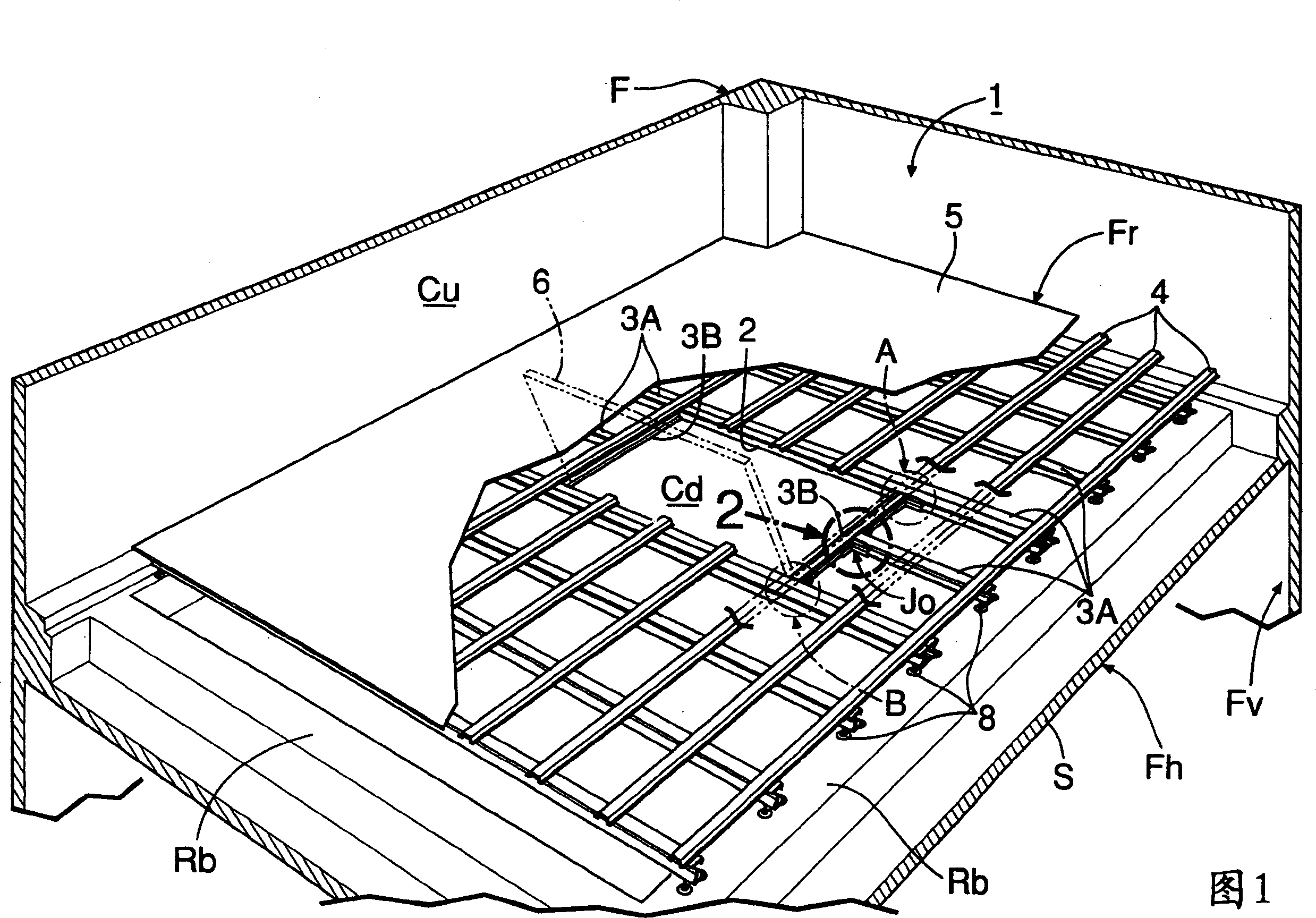
[0017] First, with reference to Figs. 1 to 5, an embodiment in which the beam connection structure of the present invention is implemented on the floor of a multi-story house having a concrete body with an inverted beam structure will be described.

[0018] In Fig. 1, the concrete body F constituting the skeleton of a multi-story house or the like has a horizontal body part Fh extending horizontally and dividing the house into upper and lower levels, and a horizontal body part Fh extending vertically and dividing the adjacent horizontal body part. The vertical body part Fv and the horizontal body part Fh which are connected to each other between the parts Fh are integrally provided with a plurality of reverse beams Rb protruding upward from the upper surface of the plate S to form a so-called reverse beam structur...


PUM


Abstract

In a support beam connecting structure used for a floor of a building, each of a first and a second support beam has two reference slant faces formed opposed to each other, and a joint member has connecting reference slant faces opposed to each other. The reference slant faces of one of the first and second support beams and the connecting reference slant faces of the joint member are made close contact with each other, and the one support beam and the joint member are secured to each other by a bolt and a nut, whereby the one support beam and the joint member are connected together while centering them in a vertical direction. Then, the other support beam and the joint member are secured to each other by a bolt and a nut. Therefore, when the first support beam and the second support beam, which are disposed perpendicular to each other, are connected together by the joint member, the upper faces of the first support beam and the second support beam can be made easily and precisely flush with each other on a plane.

Description

technical field [0001] The present invention relates to a connection structure of beams such as joist joists used on floors of houses and the like. Background technique [0002] Generally speaking, in multi-storey houses and other houses, the floor that separates the above-floor space and the under-floor space is horizontally erected and fixed to a plurality of joist joists in parallel on the body of a concrete body, etc., and the joists, joists, etc. The floor is laid under the floor, etc., but when the underfloor space is used as a storage space, it is necessary to open an opening on the floor that can be opened and closed by a short door. In such a case, it is necessary to reinforce the free end of the aforementioned joist joist that was cut to form the opening and become a cantilever shape, and another joist joist is arranged in a direction intersecting the joist joist, The joist joist around the opening is reinforced by integrating the other joist joist with the aforem...

Claims


Application Information

Patent Timeline
IPC IPC(8): E04B5/02E04B1/24E04B1/58E04B5/10E04B5/14E04C3/04E04F15/00
CPCE04C2003/0473
Inventor 饭田郁夫冲田广司
Owner RENACE KENKYUSHO
Why Eureka
Try Eureka