Non-inserted core optical fiber equipment used for optical back plate connecting system

A technology for optical backplanes and connecting devices, applied in the field of optical interfaces, can solve problems such as increasing installation costs

Active Publication Date: 2004-06-23
格芯公司
View PDF0 Cites 9 Cited by
  • Summary
  • Abstract
  • Description
  • Claims
  • Application Information

AI Technical Summary

Problems solved by technology

Also, even where non-epoxy field terminations are used, it still takes 5 to 10 minutes (or longer) to perform duplex fiber optic connectors (compa

Method used


Image

  • Non-inserted core optical fiber equipment used for optical back plate connecting system
  • Non-inserted core optical fiber equipment used for optical back plate connecting system
  • Non-inserted core optical fiber equipment used for optical back plate connecting system

Examples


Embodiment Construction

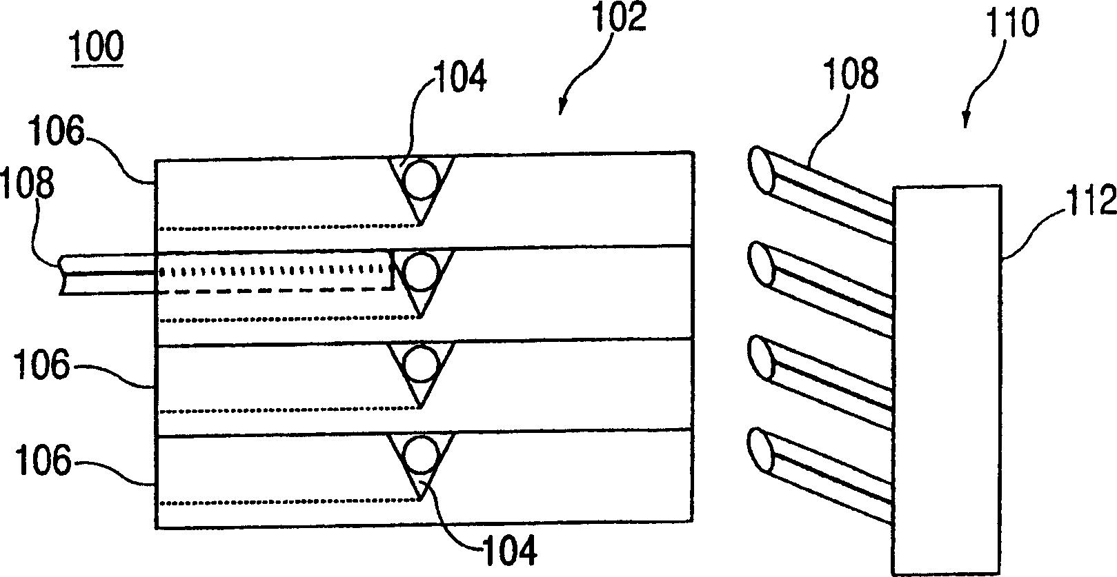
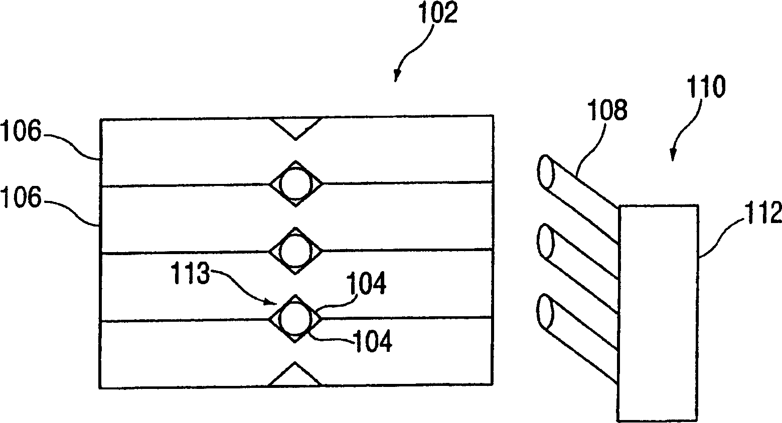
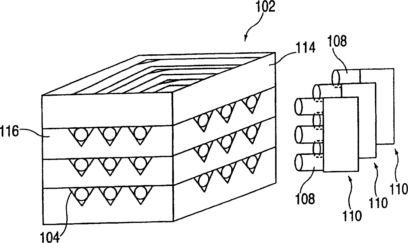
[0018] First refer to figure 1 , which shows a ferruleless optical connection device 100 suitable for use in an optical backplane connection system according to an embodiment of the present invention. The device 100 includes a stacked silicon stack assembly 102 having a plurality of light guide housing components in figure 1 V-shaped grooves 104 are formed in each successive layer 106 of the laminated assembly 102 . Each trench 104 may be formed within silicon stack assembly 102 by a technique such as etching, and is configured to receive a single light guide (eg, optical fiber 108 ) inserted therein. It should be noted that the optical fiber 108 is inserted within a single groove 104 without the use or presence of a ferrule or other cylindrical plug attached thereto. Furthermore, the optical fibers 108 are substantially cantilevered in free space prior to insertion into the stack 102, and alignment is achieved therein by the V-grooves 104 themselves.

[0019] In particular...


PUM


Abstract

A ferrule-less optical backplane connector assembly includes a substrate having at least a pair of optical guide receiving structures formed therein, the pair of optical guide receiving structures further being formed at substantially a right angle with respect to one another so as to guide a corresponding first and second optical guide into optical alignment with one another.

Description

technical field [0001] The present invention relates generally to optical interfaces for data communications, and more particularly to a ferrule-less optical fiber apparatus for use in optical backplane connection systems. Background technique [0002] There have been many recognized benefits to replacing the copper leads of printed circuit boards (PCBs) used in computer and networking equipment with optical fiber. These potential benefits include increased bandwidth and data transfer speed, overcoming bottlenecks in the process structure, immunity to electromagnetic interference and reduced radiated noise from the system, reduced latency by eliminating optical / electrical (OLE) Higher packing density at lower pin cost and new processor interconnect technologies such as meshed rings are possible. These and other factors directly contribute to the performance of the computer system (for example, increasing the processing power of MIPS (million instructions per second) or FLOP...

Claims


Application Information

Patent Timeline
IPC IPC(8): G02B6/36G02B6/43
CPCG02B6/43G02B6/3652G02B6/3676G02B6/3636G02B6/3608
Inventor 卡梅伦·J·布鲁克斯菲利普·G·埃玛卡西梅尔·M·德库萨蒂斯劳伦斯·雅各博维茨约翰·U·尼克博克
Owner 格芯公司
Why Eureka
Try Eureka